
Flotage trapping device using electrostatic field

a trapping device and electrostatic field technology, applied in the direction of electrode cleaning, magnetic separation, electric supply techniques, etc., can solve the problems of more collectors, collectors becoming expensive, and the trapping device using electrostatic field takes a lot of trouble over maintenan

Active Publication Date: 2010-11-16
TRINC
View PDF14 Cites 9 Cited by
  • Summary
  • Abstract
  • Description
  • Claims
  • Application Information

AI Technical Summary

Benefits of technology

[0013]There is also provided a flotage trapping device using electrostatic field which comprises a body including a power source portion and a boosting portion for boosting, fed from said power source portion, and a collector portion including a collector to which the plus and / or minus high voltage obtained from said boosting portion is applied, said collector portion being formed as a collector cassette by electric conductor(s) or conductive flat plate comprising one plus and / or minus electric conductor juxtaposed in parallel by fold-back in which the high voltage transferred from the high voltage generating unit is applied to one end of the electric conductor or conductive flat plate of the collector and the high voltage is received at the other end of the electric conductor or conductive flat plate of the collector and the received voltage is compared with preset values, whereby errors or malfunctions such as breaking of collector, short circuit to the earth, leakage, non-connection of collector or loose connection between the body and the collector can be detected and thus the power source is controlled.

Problems solved by technology

However, although the collector for trapping the flotage such as dust, mist should be periodically maintained, there is a problem in that the flotage trapping device using electrostatic field takes a lot of trouble over maintenance more than a filter-type device.
Furthermore, if the collector portion is made by a rigid plate the collector portion becomes expensive.
Particularly, there is a problem in that the more the collector is made to be large in order to enhance capability of trapping the flotage, the more the collector is expensive.
However, there are problems in that if the electric conductors are soldered at many places to form a collector portion, soldered portions are at risk for leakage and it is difficult to adjust the tension of wiring to be in uniformity, so the cost for assembling a collector portion become expensive.
Furthermore the flotage trapping device which has a collector portion traps or captures the flotage by applying high voltage to it from power supply of its main body, has more problems such as it can't detect the disconnection of the electric wire in the collector portion, uninstallation of the collector portion, bad connection of the connecter between the collector portion and main body, and in addition if short circuit or leakage to the earth occurs at the portion where the high voltage is applied these can not be detected as well.
Moreover, when a plurality of flotage trapping devices are installed to trap the flotage such as dust or mist or the like in more large area, an outlet for power source should be prepared for each device, and if an AC adapter for use with the outlet is prepared for each flotage trapping device the additional cost of AC adapters is generated.
It takes a lot of trouble and there would be oversight.

Method used


Image

  • Flotage trapping device using electrostatic field
  • Flotage trapping device using electrostatic field
  • Flotage trapping device using electrostatic field

Examples


first embodiment

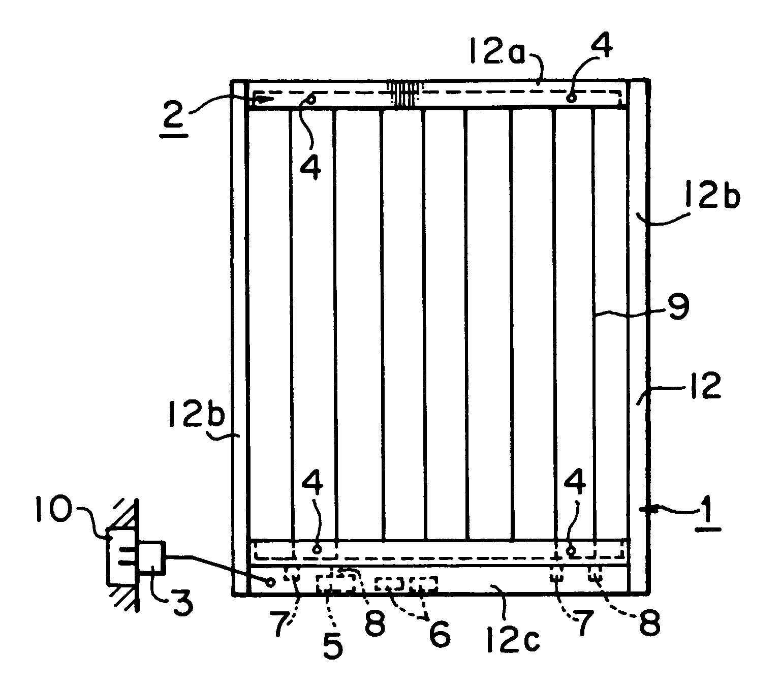
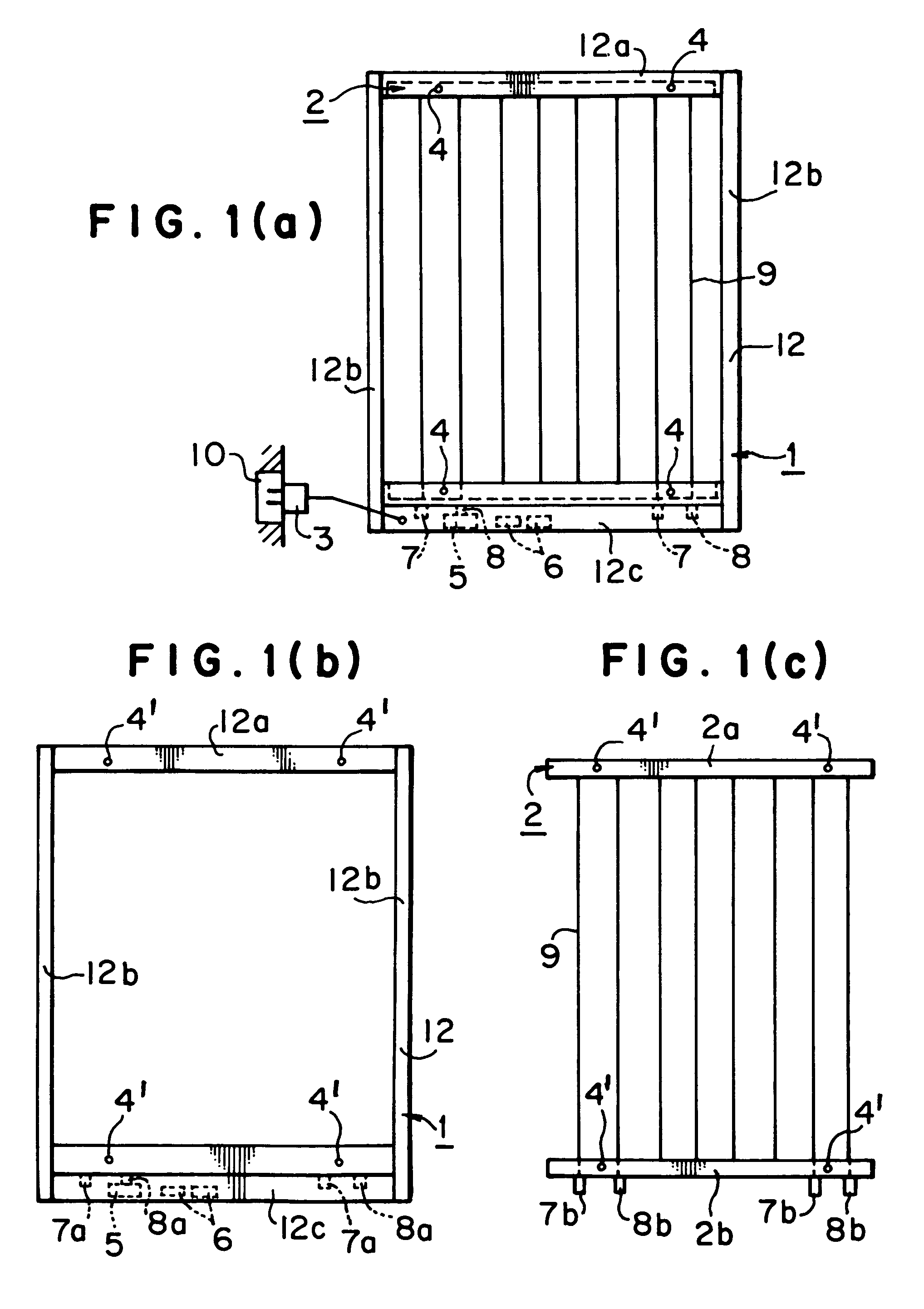
[0023]FIG. 1 shows a first embodiment of a flotage trapping device using electrostatic field according to the present invention, FIG. 1a shows the state that the body of flotage trapping device and a collector cassette are assembled, FIG. 1b shows the body of flotage trapping device, and FIG. 1c shows the collector cassette.

[0024]As shown in FIGS. 1a-1c, a body 1 has a rectangular frame 12, that is, an upper frame portion 12a, side frame portions 12b on both sides, and a bottom frame portion 12c. The upper frame portion 12a is formed with pin holes 4′ in which fixing pins 4 are inserted to fix a collector cassette 2 to the body 1. The bottom frame portion 12c is formed with pin holes 4′ in which fixing pins 4 are inserted to fix a collector cassette 2 to the body 1, and is provided with connecters 7a and 8a of a plus high voltage connecter 7 and a minus high voltage connecter 8 on the body side. Furthermore, the bottom frame portion 12c is provided with a power source unit 5 for gen...

second embodiment

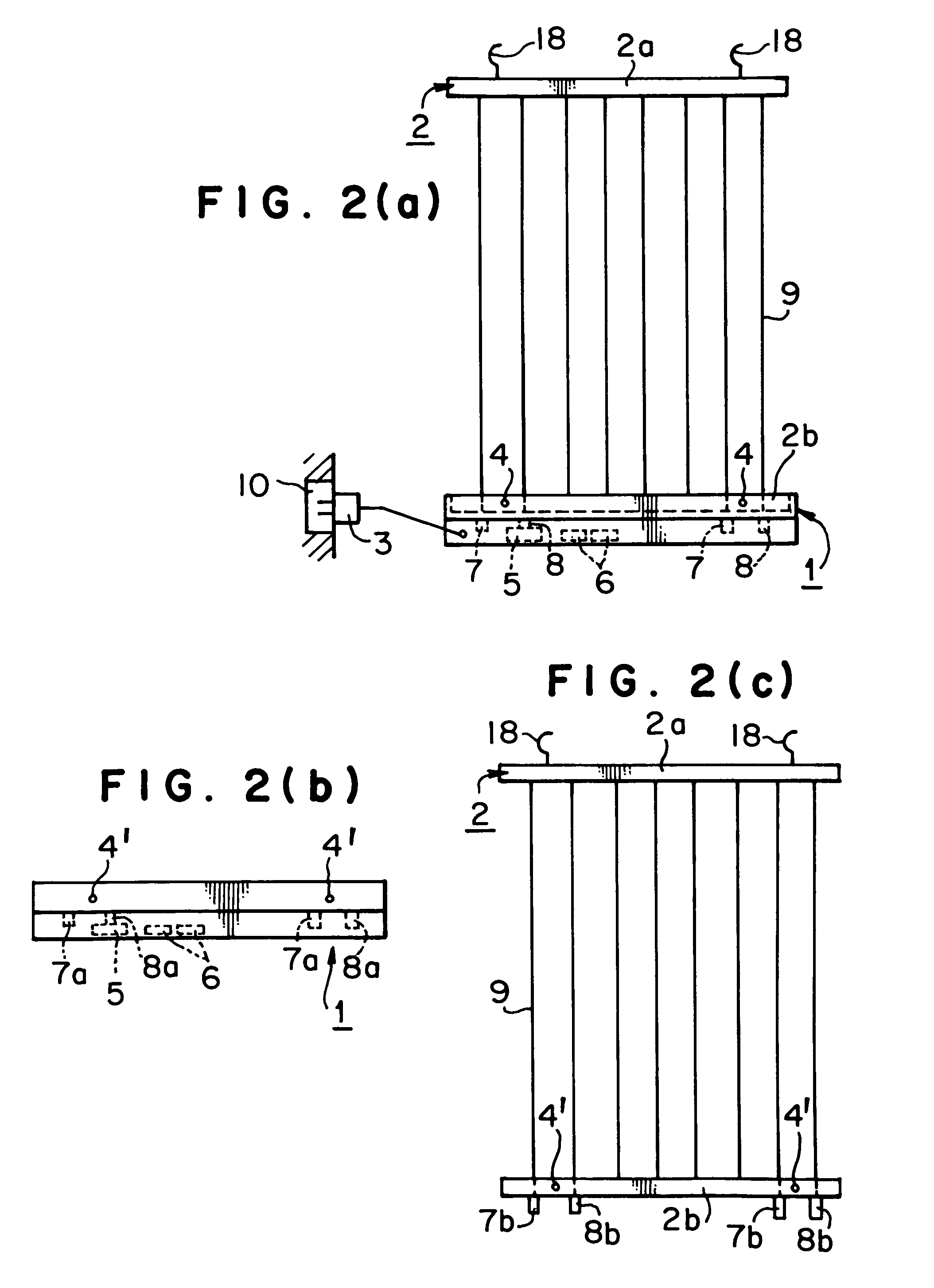
[0028]FIG. 2 shows a second embodiment of a flotage trapping device using electrostatic field according to the present invention, FIG. 2a shows the state that the body of flotage trapping device and a collector cassette are assembled, FIG. 2b shows the body of flotage trapping device, and FIG. 2c shows the collector cassette.

[0029]As shown in FIGS. 2a to 2c, the body 1 is not provided with frame and has only a member corresponding to the bottom frame portion 12c in the first embodiment. The collector cassette 2 is not formed with pin holes 4′ at its upper portion 2a and instead is provided with hooks 18 which are hanged at installation location. The other portions of the collector cassette 2 are similar to those of the collector cassette of the first embodiment.

[0030]The body 1 and the collector cassette 2 are assembled by inserting fixing pins 4 in the pin holes 4′ of the body 1 and the pin holes 4′ of the collector cassette 2 after the connecters 7a and 8a of the body 1 and the co...

third embodiment

[0033]FIG. 3 shows a third embodiment of a flotage trapping device using electrostatic field according to the present invention, FIG. 3a shows the flotage trapping device viewed from its front side, and FIG. 3b shows the flotage trapping device viewed from its side.

[0034]The third embodiment is characterized by the construction in which the plus or minus high voltage collector 9 comprises one electric conductor. Since the plus or minus high voltage collector 9 comprises one electric conductor, juxtaposed electric conductors which would be individually soldered to form the collector cassette 2 are not required, and thus man hour for assembling can be reduced and electric leak at the soldered portions can be eliminated.

[0035]As shown in FIG. 3, the electric wire for forming collector 9 is folded back through pulleys 11 which are rotatably attached at the upper portion 2a. Both ends of electric wires of collector 9 are connected to the connecters provided at the bottom portion 2b. When...


PUM


Abstract

There is provided a flotage trapping device using electrostatic field. The flotage trapping device has a body including a power source portion and a boosting portion fed from the power source portion, and a collector portion including a collector to which the plus and / or minus high voltage obtained from the boosting portion is applied. The collector portion is formed as a collector cassette by unitizing the collector portion in the form of a cassette. A fixing mechanism is provided between the body and the collector cassette for connecting and disconnecting the body and the collector cassette through one-touch operation. The electric connector for high voltage is provided between the body and the collector cassette for electrically connecting and disconnecting the body and the collector cassette through one-touch operation. As a result the collector cassette is detachably mounted on the body.

Description

TECHNICAL FIELD[0001]This invention relates to a flotage trapping device which traps or captures the flotage such as dust or mist using electrostatic field.BACKGROUND OF INVENTION[0002]As a flotage trapping device which traps or captures the flotage such as dust or mist using electrostatic field, the device in which dust, mist or the like is trapped or captured by applying high voltage to its collector portion, or the device in which an ion generating device is disposed adjacent to the flotage trapping device so that floating dust or mist are forcibly charged in order to enhance efficiency of trapping the flotage on the voltage applied collector portion has been developed.[0003]The flotage trapping device using electrostatic field has merits in that it does not require a blow fan by which wind is forcibly blown to a filter, different from trapping device using a filter, and the effects given to a clean environment can be suppressed to the minimum since dust is not wound up due to ca...

Claims


Application Information

Patent Timeline
Patent Type & Authority Patents(United States)
IPC IPC(8): B03C3/68B03C3/86
CPCB03C3/74B03C3/88B03C2201/28
Inventor TAKAYANAGI, MAKOTOTAKAGI, AKITOSHIIMAGAWA, YASUNORI
Owner TRINC
Learn More