Motor winding bobbin and terminal structure thereof

a technology of winding bobbins and motors, which is applied in the direction of dynamo-electric machines, synchronous generators, electrical apparatuses, etc., can solve the problems of reducing product reliability, increasing production costs, and the terminal structure b>1/b> is likely to depart from the winding structure, so as to increase the connecting force, reduce the effect of applying force and accurately positioning

Inactive Publication Date: 2009-03-26
DELTA ELECTRONICS INC
View PDF2 Cites 3 Cited by
  • Summary
  • Abstract
  • Description
  • Claims
  • Application Information

AI Technical Summary

Benefits of technology

[0010]In view of the foregoing, the present invention is to provide a motor winding bobbin and a terminal structure thereof capable of increasing the connecting strength there between, thereby preventing loose connections or departure, ensuring the product reliability, simplifying the man manufacturing process, and decreasing the cost.
[0011]In addition, the present invention is also to provide a terminal structure that efficiently buffers improper actions imposed on the motor winding bobbin to ensure the product reliability.
[0015]As mentioned above, the terminal structure of the present invention has a fixing pattern that can increase the connecting force between the terminal structure and the electronic device so that the terminal structure cannot be easily pulled away from the electronic device. Since the terminal structure of the present invention has a positioning portion, the connecting depth of the terminal structure in the connecting end of the electronic device can be accurately positioned. The buffering portion of the terminal structure can greatly reduce the force applying on the contact portion between the terminal structure and the connecting end. The above-mentioned features of the present invention can prevent damages to the electronic device, increase the stability of the system, simplify the manufacturing process, and decrease the production cost.

Problems solved by technology

This may result in damages to the winding structure 1, thereby making the terminal structure loose, increasing the production cost and reducing the product reliability.
For example, when the insertion of the terminal structure 1 into the winding structure 2 is not deep enough, the terminal structure 1 is likely to depart from the winding structure because of insufficient support.
However, this method largely increases the production processes involved therein.
Thus, both the production time and cost increase.

Method used


Image

  • Motor winding bobbin and terminal structure thereof
  • Motor winding bobbin and terminal structure thereof
  • Motor winding bobbin and terminal structure thereof

Examples


Embodiment Construction

[0021]The present invention will be apparent from the following detailed description, which proceeds with reference to the accompanying drawings, wherein the same references relate to the same elements.

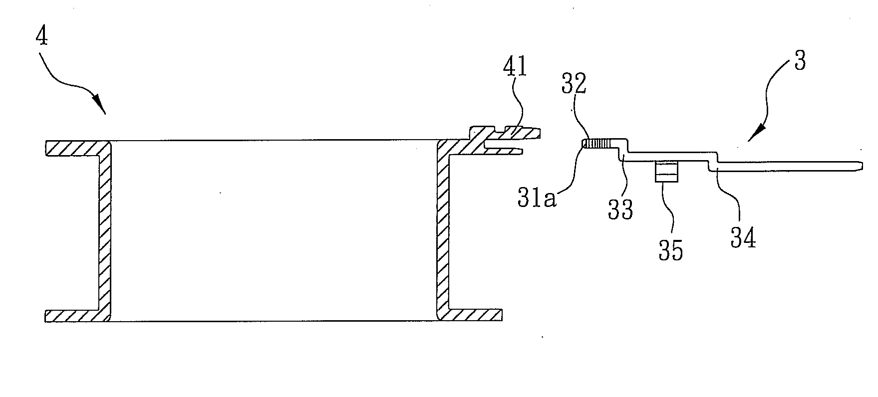
[0022]As shown in FIG. 2A and FIG. 2B, a terminal structure 3 according to a preferred embodiment of the present invention is inserted into a connecting end 41 of an electronic device 4. The terminal structure 3 has a fixing portion 32 and at least one positioning portion 33. The terminal structure 3 can be integrally formed. More explicitly, the fixing portion 32 and the positioning portion 33 are integrally formed as a single unit. In this embodiment, the electronic device 4 is a motor winding structure. The material of the terminal structure 3 is gold, silver, copper, aluminum or any other conductive material.

[0023]The fixing portion 32 is used to connect with the connecting end 41 of the electronic device 4. The fixing portion 32 is disposed on one end of the terminal structure 3 ...


PUM


Abstract

A motor winding bobbin and terminal structure there are disclosed. The terminal structure includes a fixing portion and at least one positioning portion. The fixing portion is disposed at one end of the terminal structure and has at least one fixing pattern. The fixing portion is connected with a connecting end of the motor winding structure. The positioning portion is disposed adjacent to the fixing portion and urged against the motor winding structure for positioning the fixing portion while it is connected with the connecting end.

Description

CROSS REFERENCE TO RELATED APPLICATIONS[0001]This Non-provisional application claims priority under 35 U.S.C. §119(a) on Patent Application No(s). 096135409, filed in Taiwan, Republic of China on Sep. 21, 2007, the entire contents of which are hereby incorporated by reference.BACKGROUND OF THE INVENTION[0002]1. Field of Invention[0003]The present invention relates to a motor winding bobbin and a terminal structure thereof and in particular to a terminal structure capable of firmly connecting with the motor winding bobbin.[0004]2. Related Art[0005]The connecting methods between components of an electronic device and terminals are optional depending on the materials and applications. For example, the connection of metals is usually done by soldering. The connection of plastic components is usually done by melting or via an adhesive. In addition, the connection between the plastic component and metal terminal is also common in motors and its output terminals.[0006]As shown in FIG. 1A a...

Claims


Application Information

Patent Timeline
Patent Type & Authority Applications(United States)
IPC IPC(8): H02K3/46
CPCH02K3/52
Inventor HUANG, WEN-SHIHSU, CHIN-CHUYANG, CHUN-HUAHSU, CHIA-YING
Owner DELTA ELECTRONICS INC
Why Eureka
Try Eureka