Wireless surface acoustic wave-based proximity sensor, sensing system and method

a technology of proximity sensor and surface acoustic wave, applied in the field of proximity sensors, can solve the problems of high wire requirements, high undesirable weight of isolation shielding or shielding, and currently available options have their own, and achieve the effect of fewer mask and processing steps and simple device fabrication

Inactive Publication Date: 2010-11-16
ROSEMOUNT AEROSPACE
View PDF8 Cites 1 Cited by
  • Summary
  • Abstract
  • Description
  • Claims
  • Application Information

AI Technical Summary

Benefits of technology

[0010]The subject invention is directed to a wireless proximity sensor, wireless proximity sensing system, and method that uses SAW technology in conjunction with magnetostrictive materials to detect the position of objects. Such a sensor and sensing system is advantageous because it eliminates the need for heavy, complex and difficult to maintain sensors and sensor wiring. In addition, the device fabrication is simpler and requires fewer mask and processing steps with the added benefit of small proximity sensor device dimensions.

Problems solved by technology

The heavy isolation armor or shielding and wire required are highly undesirable in the field of weight sensitive aircraft design.
While the aviation industry is looking for alternatives, the currently available options have their own disadvantages.
One alternative is a voltage sensing capacitive type sensor, which may require heavy isolation hardware as a result of capacitive coupled voltage due to electromagnetic interference.
Conductive fluids and water condensation pose additional problems for capacitive type sensors.
Magnetic or optical interrupt switches, although much lighter due to less shielding, are failure prone in the harsh conditions of aviation.
Further, magnetic switches attract ferrous metal filings that inhibit the detection of a near / far condition, resulting in false condition reporting and low reliability.
Optical switches suffer from foreign object contamination, such as dirt, which again reduces the performance of the device.
Wire requires a number of aircraft interactions for installation that drives up cost in both design and manufacturability.
Additionally, wire is heavy and difficult to troubleshoot when sensor operation fails.
This configuration however, has several drawbacks that do not make it ideal for proximity sensing applications.
These drawbacks include, but are not limited to, the stationary positioning of the electromagnet and the weight of the wiring necessary to supply DC current to the poles of the electromagnet.

Method used


Image

  • Wireless surface acoustic wave-based proximity sensor, sensing system and method
  • Wireless surface acoustic wave-based proximity sensor, sensing system and method
  • Wireless surface acoustic wave-based proximity sensor, sensing system and method

Examples


Embodiment Construction

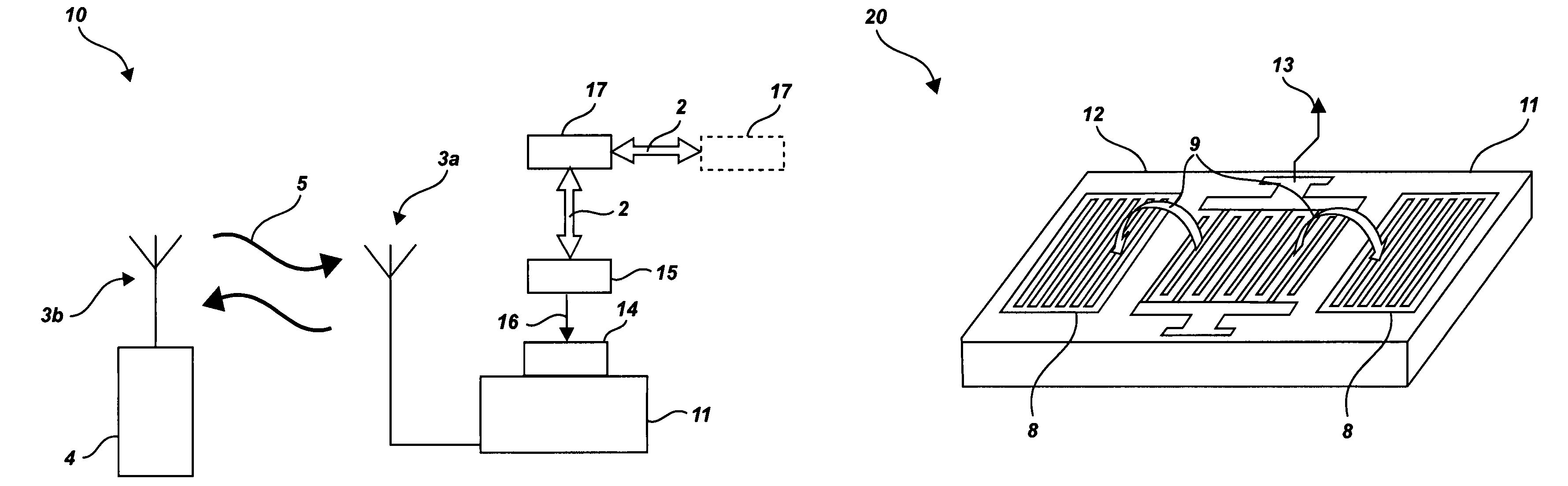
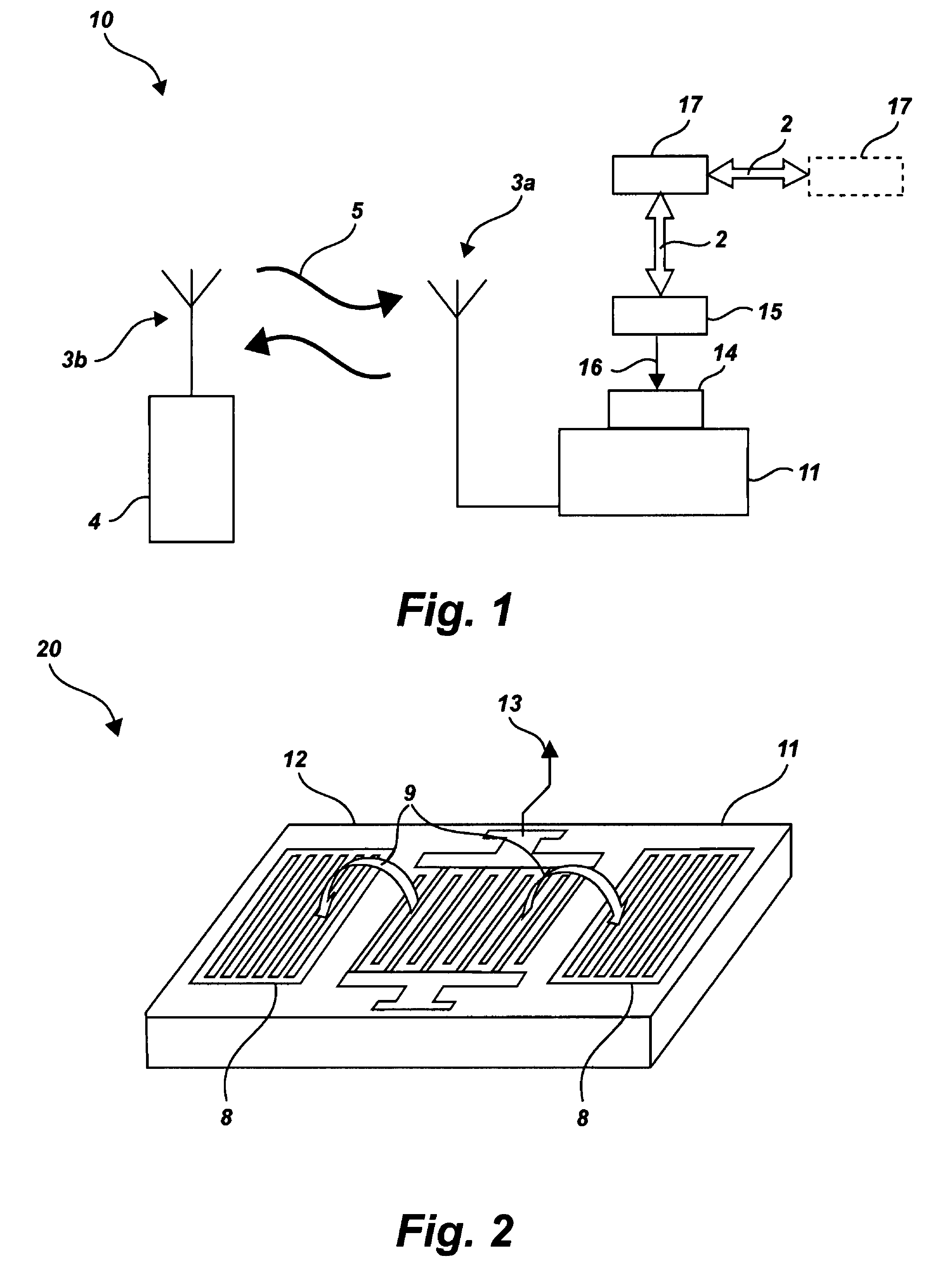
[0026]The subject invention relates to a wireless proximity sensor, system and method for detecting the presence of both moving and stationary objects. FIG. 1 shows a schematic representation of the proximity sensing system 10 of an embodiment of the present invention. The transceiver 4 sends through its associated antenna 3b a request for information 5 about a position of an object. The request for information 5 sent by the transceiver 4 powers the SAW device, enabling it to operate wirelessly within the proximity sensing system 10.

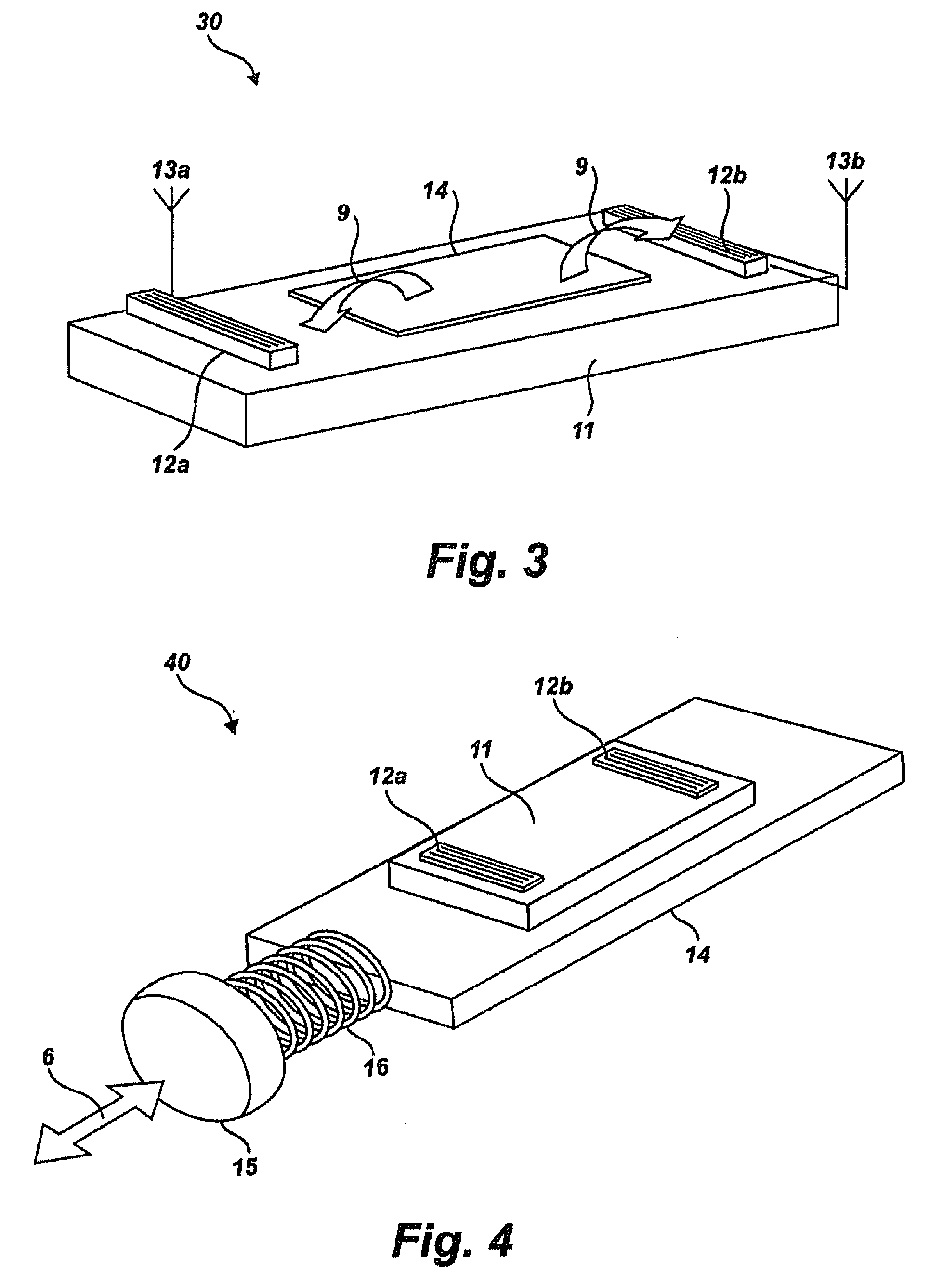
[0027]The wireless proximity sensing system 10 generally includes one or more first antennas 3a and one or more second antennas 3b. The first antenna 3a is associated with the proximity sensor for wirelessly receiving the request signal from the transceiver 4 and transmitting a response that includes information about a position of an object based on a location of the magnet 15 relative to the body 11 of the SAW device and relative to the sensing element...


PUM


Abstract

The subject invention is related to wireless proximity sensor and sensing system for detecting the position of an object. The system includes a transceiver for providing wireless communication with a passive wireless surface acoustic wave (SAW) proximity sensor. The wireless proximity sensor receives a wireless signal from the transceiver, which powers the SAW device and in turn transmits a signal back to the transceiver that includes information about the position of an object. The wireless proximity sensor uses one or more SAW devices with a sensing element made of magnetostrictive material, in conjunction with one or more magnets and one or more targets that are positioned relative to an object. The movement of the target(s) in relation to the proximity sensor operatively produces a mechanical response due to the shift in the magnetic field of the sensing element. The sensing element in turn enhances the magnetic field of the SAW device to which it is attached, and this information is transmitted to the transceiver as information about the position of an object.

Description

BACKGROUND OF THE INVENTION[0001]1. Field of the Invention[0002]The subject invention is related to proximity sensors for detection of a position of an object, and more particularly, to a wireless proximity sensor and sensing system that uses surface acoustic wave (SAW) technology to reduce weight and complexity to meet the rigorous demands of the aviation industry and other position sensing applications.[0003]2. Description of the Related Art[0004]Proximity sensors have long been used to indicate the position of an object on an aircraft or other vehicle (e.g., whether a door or hatch is open or closed). These proximity sensors are typically the current sensing induction type and heavily armored for isolation. The proximity sensor generates an electromagnetic field to sense metal objects passing within a few tenths of inches.[0005]The heavy isolation armor or shielding and wire required are highly undesirable in the field of weight sensitive aircraft design. By one estimate for fixe...

Claims


Application Information

Patent Timeline
Patent Type & Authority Patents(United States)
IPC IPC(8): G01B7/00H01L41/00G01R33/038H01L41/12
CPCH03K17/94H03K17/95H03K17/97H03K2217/96011
Inventor SPIVAK, ALEXANDERLIN, CHUANG-CHIA
Owner ROSEMOUNT AEROSPACE
Why Eureka
Try Eureka