
MRI test fixture

a test fixture and mirror technology, applied in the direction of magnetic measurement, instruments, measurement devices, etc., can solve the problems of destroying imaging data, ghosting, blurring and other artifacts in the resultant image, and affecting the accuracy of the results

Inactive Publication Date: 2010-11-16
FONAR
View PDF40 Cites 130 Cited by
  • Summary
  • Abstract
  • Description
  • Claims
  • Application Information

AI Technical Summary

Benefits of technology

The system effectively evaluates and corrects deviations in MRI system performance, ensuring image accuracy and reliability by providing standardized testing procedures and monitoring magnetic field stability, thereby preventing severe image artifacts.

Problems solved by technology

Deviations from proper performance can arise in any of the subsystems or components of the MRI system due to component degradation, power supply fluctuations, drift of analog components, environmental fluctuations, magnet drift and system or component failure, for example.
Temperature fluctuations due to the changes in temperature during the course of a day or air conditioning, are also common environmental disturbances.
Disruptions or drift in the primary magnetic field or the gradient magnetic fields, may cause ghosting, blurring and other artifacts in a resulting image.
In severe cases, the imaging data may be completely destroyed.
Deviations from the expected response indicate a problem with the MRI system and may suggest where the problem is located.

Method used


Image

  • MRI test fixture
  • MRI test fixture
  • MRI test fixture

Examples


Embodiment Construction

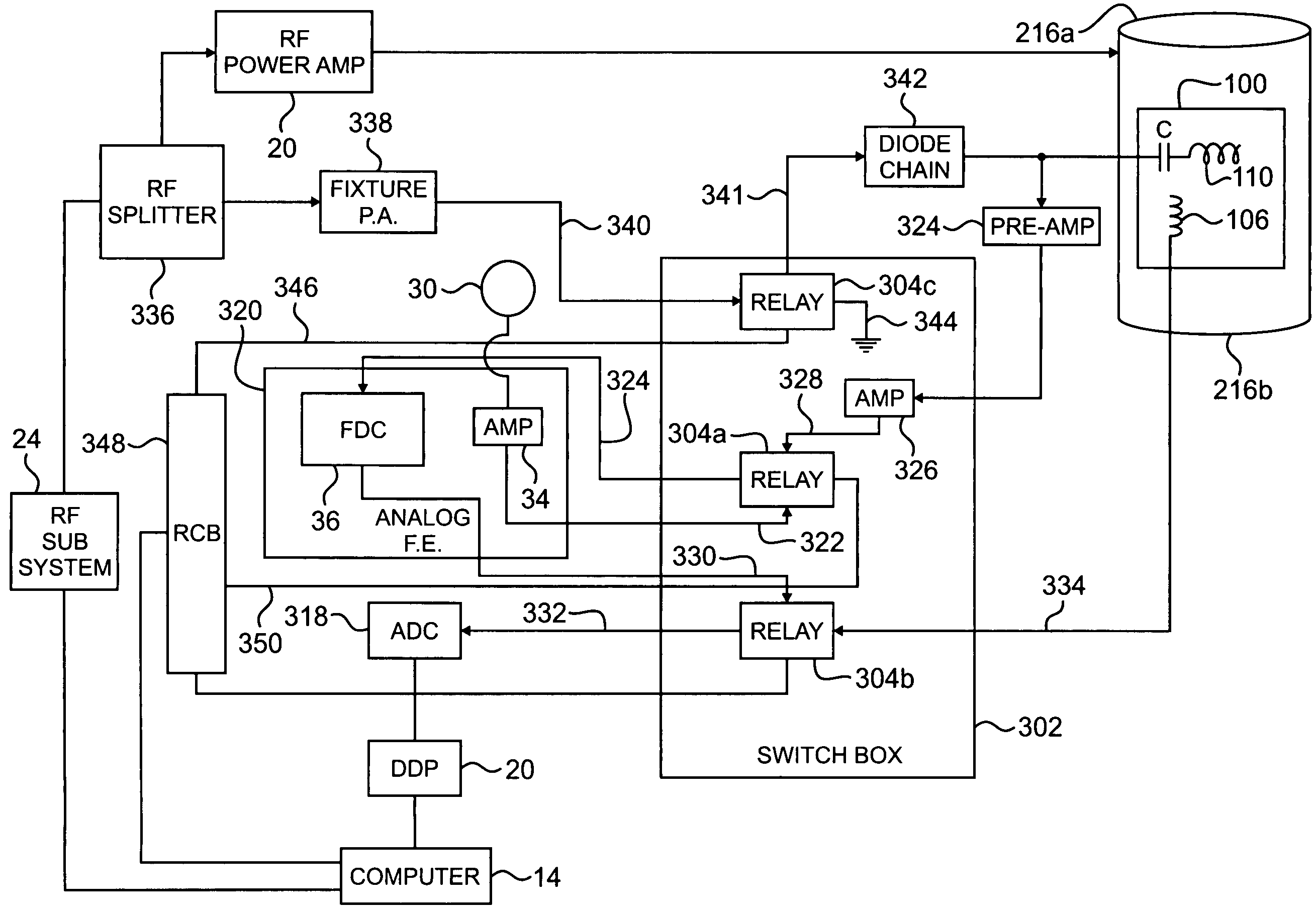
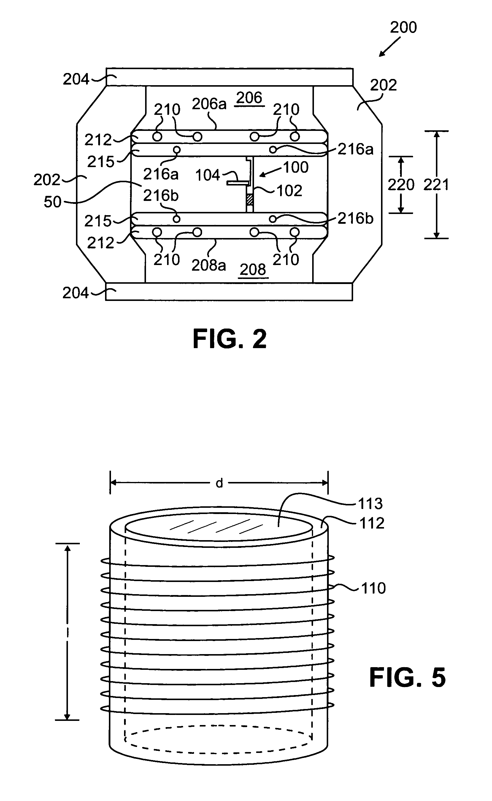
[0029]FIG. 2 is a side view of one embodiment of a test fixture 100 deployed in the imaging volume 220 between the poles of a magnet assembly of an Open Magnetic Resonance Imaging (“MRI”) System 200, in accordance with the present invention. In a preferred embodiment, the test fixture 100 comprises a vertically extending main body portion 102 and an arm 104.

[0030]In one embodiment, the Open MRI System 200 comprises a magnet assembly comprising a ferromagnetic frame supporting ferromagnetic poles. The ferromagnetic frame may comprise ferromagnetic elements 202 connected at their ends to opposing ferromagnetic pole supports 204. The ferromagnetic pole supports are plates that support upper and lower ferromagnetic poles 206, 208. The supporting elements may be ferromagnetic plates, as described in U.S. Pat. No. 6,201,394 B1, assigned to the assignee of the present invention and incorporated by reference herein, for example, or four ferromagnetic posts connected to the corners of the po...


PUM


Abstract

In one example, a magnetic resonance imaging (“MRI”) system comprises a magnetic resonance imaging assembly defining a gap region, a transmitting coil proximate the gap region, and at least one test coil separate from the transmitting coil. The at least one coil is mechanically coupled to the assembly during imaging and the at least one test coil is selectively electrically coupled to the assembly to collect test data. The at least one coil may be coupled to a test fixture coupled to the assembly. The test fixture may be deployable from a first position to a second position for collection of test data. The at least one coil may comprise a first test coil and a second test coil. Methods are also disclosed.

Description

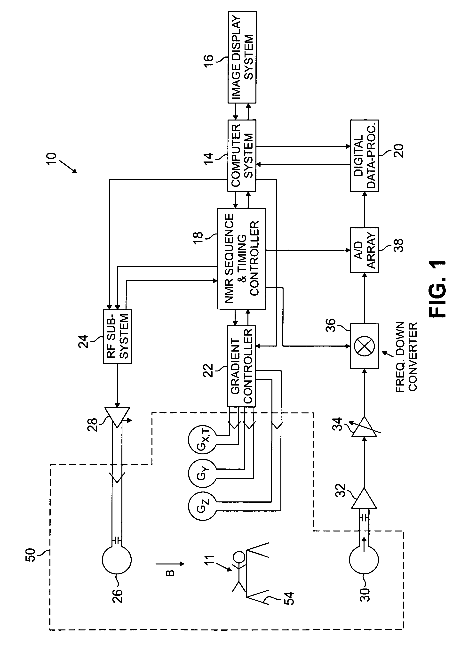
[0001]The present application is a division of U.S. patent application Ser. No. 09 / 992,733, which was filed on Nov. 14, 2001, is assigned to the assignee of the present application, and is incorporated by reference hereinFIELD OF THE INVENTIONBackground of the Invention[0002]Magnetic Resonance Imaging (“MRI”) is a highly useful technique for diagnosing abnormalities in biological tissue. Medical MRI requires creation of a substantially constant “primary” magnetic field, which passes through a patient's body. The patient is also exposed to electromagnetic waves in the radio frequency range, which vary with time in particular patterns. Under the influence of the magnetic fields and the radio waves, certain atomic nuclei within the patient's tissues resonate and emit other radio frequency waves, referred to as MR signals. Linear time varying “gradient” magnetic fields are typically superimposed on the primary field, based on the desired scanning sequence, to encode the MR signals in sp...

Claims


Application Information

Patent Timeline
Patent Type & Authority Patents(United States)
IPC IPC(8): G01V3/00
CPCG01R33/58
Inventor DAMADIAN, RAYMOND V.WAHL, HUGHASPELUND, REINKELLY, JAMES
Owner FONAR
Learn More