
Tiling system for 3D rendered graphics

a technology of 3d rendering and tile list, applied in the field of 3d computer graphics image generation, can solve the problems of not always working, wasting time, memory and processing effort, and storing these very small primitives in tile list, so as to achieve the effect of safe use of lower precision calculations

Active Publication Date: 2010-11-16
IMAGINATION TECH LTD
View PDF21 Cites 17 Cited by
  • Summary
  • Abstract
  • Description
  • Claims
  • Application Information

AI Technical Summary

Benefits of technology

[0026]As a first embodiment of the invention, a method and an apparatus are presented which safely use lower precision calculations. Furthermore, the system may be tuned to trade-off accuracy, i.e. implementation cost, of the maths against the increased likelihood of additional redundant tiles. The system also has the advantage of using a uniform testing procedure for all edges / tiles.
[0027]In a second embodiment of the invention, we have also appreciated that a method of directly tiling line segment primitives that takes advantage of special properties, is desirable. The method presented is cheaper than converting the primitive to an equivalent polygon or polygons.

Problems solved by technology

Storing these very small primitives in tile lists is an unnecessary use of time, memory, and processing effort.
In these cases, however, a bounding box rejection test will fail to cull these primitives.
Unfortunately, this does not always work as an object may have been modelled by, say, by tessellation to small triangles—rejecting all small triangles could easily make the entire object disappear!
(1) The precision of the mathematics used to perform the rejection calculations must be at least as accurate as, or at least give identical results to, that used by the rendering system when that decides which pixels a primitive covers.
This may seem like a triviality, but in practice it may be more complicated.
Doing this reduces the cost of the hardware needed when rendering inside the tile, however, it would make it very difficult and / or more expensive to have a ‘global test’ with exactly the same accuracy that can be used for the ‘tiling’ operation.
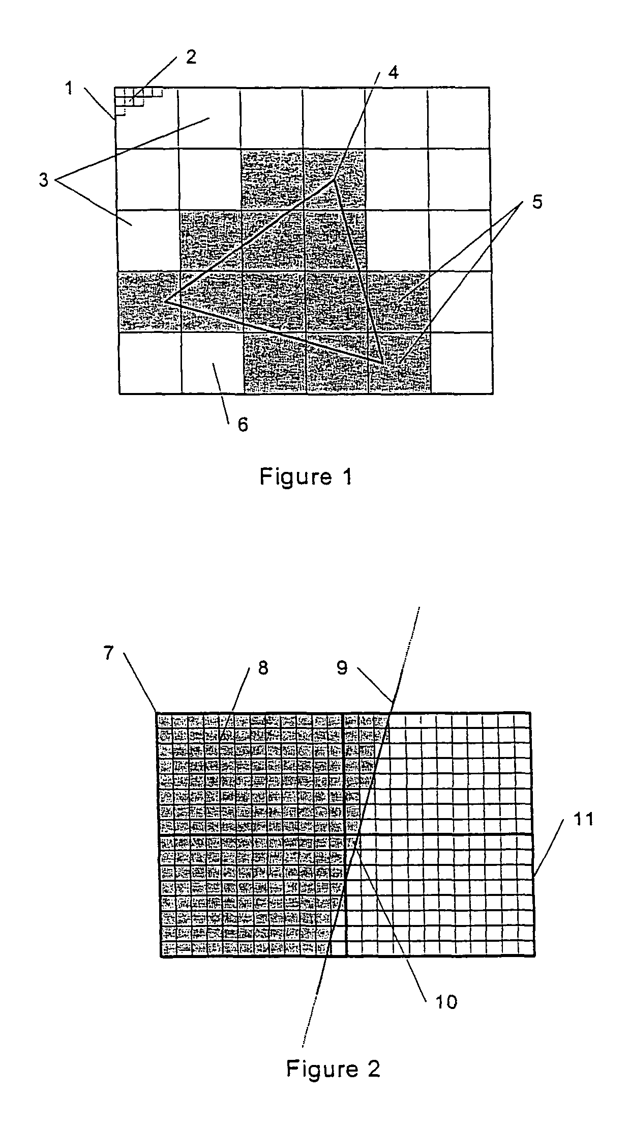
If there is any deviation in accuracy, then there is a chance that tile ‘11’ might be deemed to not include the primitive and hence cause pixel ‘10’ to be rendered incorrectly.
Even if the mathematics provides exactly the same results as that used inside the renderer, a hardware solution would require a significant amount of silicon.
An alternative could be to use fixed-point mathematics, rather than floating-point, but this incurs the problem that arbitrary polygons would have to be ‘clipped’ to the valid supported mathematical range.
This is an inconvenience, as it requires decisions on a tile-by-tile / edge-by-edge basis.
(4) The system does not attempt to address cases where ‘tiny’ primitives, e.g. those that are around the size of a pixel, are supplied to the tiling engine but don't actually get rendered.
Adding these to the tile list is thus wasted effort.

Method used


Image

  • Tiling system for 3D rendered graphics
  • Tiling system for 3D rendered graphics
  • Tiling system for 3D rendered graphics

Examples


Embodiment Construction

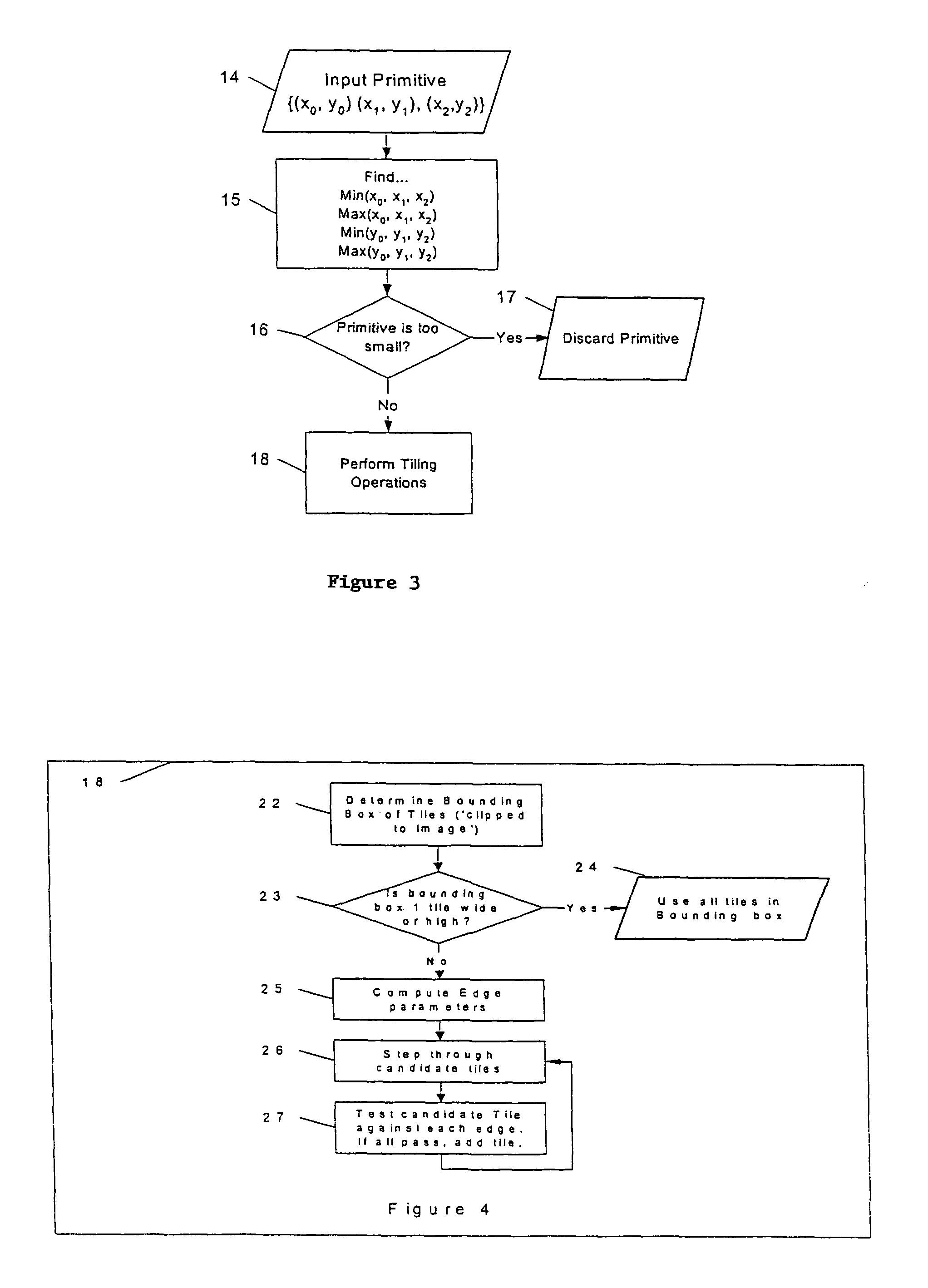
[0039]A preferred embodiment of the invention will be presented with reference to FIG. 3. As a first step, a primitive, which is preferably a triangle, is input, ‘14’.

[0040]The triangle has vertices, {(x0,y0),(x1,y1),(x2,y2)}, which are specified using IEEE, 32-bit, floating-point coordinates. As with GB2343603, the bounding box of the primitive is identified by computing the maximums and the minimums of both the projected X and Y coordinates values, ‘15’, i.e.

pxmin=min(x0,x1,x2)

pxmax=max(x0,x1,x2)

pymin=min(y0,y1,y2)

pymax=max(y0,y1,y2)

[0041]These maximums and minimums are determined at full accuracy as this is a relatively cheap operation. As an optimization, it is also possible to test for equality of the vertex positions and reject those triangles that have repeated vertex positions, as these have exactly zero area and will not contribute to the image. At this point, the invention can also reject any primitives that are trivially completely ‘off-screen’.

[0042]Using the computed bo...


PUM


Abstract

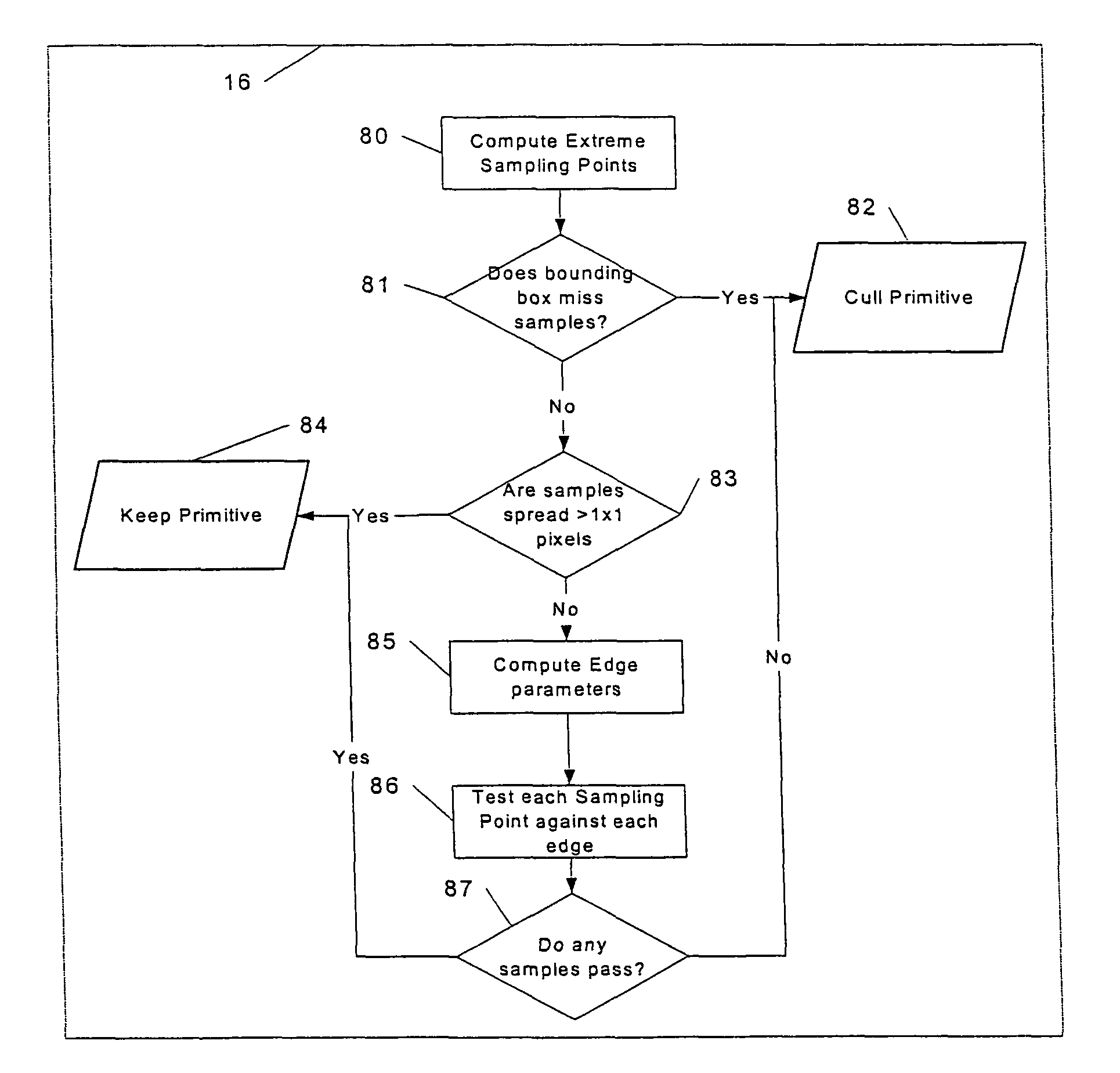
A method and an apparatus for shading three-dimensional computer graphic images is provided. A display on which the image is to be viewed is subdivided into a plurality of rectangular areas. For each rectangular area, a list of objects in the image which may be visible is determined, and this list is used to determine how the rectangular area should be shaded for display. In deriving the list of objects, a determination of maximum and minimum values for each object in x and y directions is used, and a set of sampling points is determined from these values. If a bounding box surrounding the object covers any of the sampling points, the object is added to the object list or otherwise rejected. Also provided is a method and an apparatus for testing an edge information for each object against the sample points to determine whether or not the object falls into the rectangular area in the bounding box surrounding the object. The step of testing the edge information includes shifting the edge information by a predetermined amount based on the orientation of each edge.

Description

FIELD OF THE INVENTION[0001]This invention relates to the generation of 3D computer graphics images and describes improvements to techniques described in our British patent 2343603, and earlier related patent, GB2298111.BACKGROUND OF THE INVENTION[0002]In these systems, the 2D image plane is subdivided into preferably rectangular regions of pixels and, for each such region, a list of the objects that are ‘of interest’ to that region is compiled. These regions will be referred to as tiles. When the list for a particular tile contains all such objects, the tile can be rendered entirely. An alternative scheme, (as described in our patent application PCT / GB01 / 02536), allows for partial rendering whereby the list may simply contain a subset of the required objects.[0003]It is important to have cost-effective means of determining which primitives, typically triangles and line segments, should be placed in which tiles. An example is given in FIG. 1. This shows the virtual image plane (e.g....

Claims


Application Information

Patent Timeline
Patent Type & Authority Patents(United States)
IPC IPC(8): G06T15/40G06T15/00G06T11/40G06T15/50G06T15/80
CPCG06T11/40G06T15/50G06T15/80G06T15/40G06T2210/12
Inventor FENNEY, SIMONYANG, XILE
Owner IMAGINATION TECH LTD
Learn More