Systems and methods for distributed series compensation of power lines using passive devices

a technology of distributed series and power lines, applied in emergency protective arrangements, electrical equipment, emergency circuit arrangements, etc., can solve problems such as active power flow control, grid utilization terms, and transmission constraints and bottlenecks

Active Publication Date: 2010-11-16
GEORGIA TECH RES CORP
View PDF8 Cites 221 Cited by
  • Summary
  • Abstract
  • Description
  • Claims
  • Application Information

AI Technical Summary

Problems solved by technology

Of the challenges facing utilities, a major issue is the elimination of transmission constraints and bottlenecks.
A significant issue in terms of grid utilization is active power flow control.
Congested networks limit system reliability and constrain the ability of low cost generators to provide interested customers with low-cost power.
The situation is considerably aggravated when one sees that neighboring power lines are operating below capacity, but cannot be utilized, while uncontrolled ‘loop-flows’ result in overloads on existing lines.
Series reactive compensation has rarely been used other than on long transmission lines, mainly because of high costs and complexity of achieving voltage isolation and issues related to fault management.
Even though FACTS technology is technically proven, it has not seen widespread commercial acceptance due to a number of reasons: 1) High system power ratings require the use of custom high power GTO or GCT devices with significant engineering effort—raises first cost; 2) High fault currents (60,000 Amps) and basic insulation requirements (1000 kV) stress the power electronic system, especially for series systems that are required for power flow control; 3) Utilities require higher reliability levels than what they have so far experienced with FACTS devices; 4) Required skilled work force in the field to maintain and operate the system is not within a utility's core competency normally; 5) High total cost of ownership, e.g., the Marcy convertible static compensator (CSC) cost $54 million.
However, the line is specially built for desired impedance at significant cost and reduced flexibility.
The desired impedance cannot be easily be attached to an existing line, and cannot be redeployed at a later date.
Further, the capacitances can only decrease line impedance, and are primarily used to reduce the impedance of long-haul transmission lines.
The complexity of the above-described mode of operation adds significant cost and complexity to the power transmission system.
The cost of the power converters themselves, especially when designed to operate under the harsh environmental conditions encountered on a power transmission line, is likely to be a limiting factor.
Further, the operation of power electronics converters for long periods of time (target 30 years) when suspended on a power transmission line and subject to harsh environmental conditions, will create reliability and availability problems for utilities deploying such technology.

Method used


Image

  • Systems and methods for distributed series compensation of power lines using passive devices
  • Systems and methods for distributed series compensation of power lines using passive devices
  • Systems and methods for distributed series compensation of power lines using passive devices

Examples


Embodiment Construction

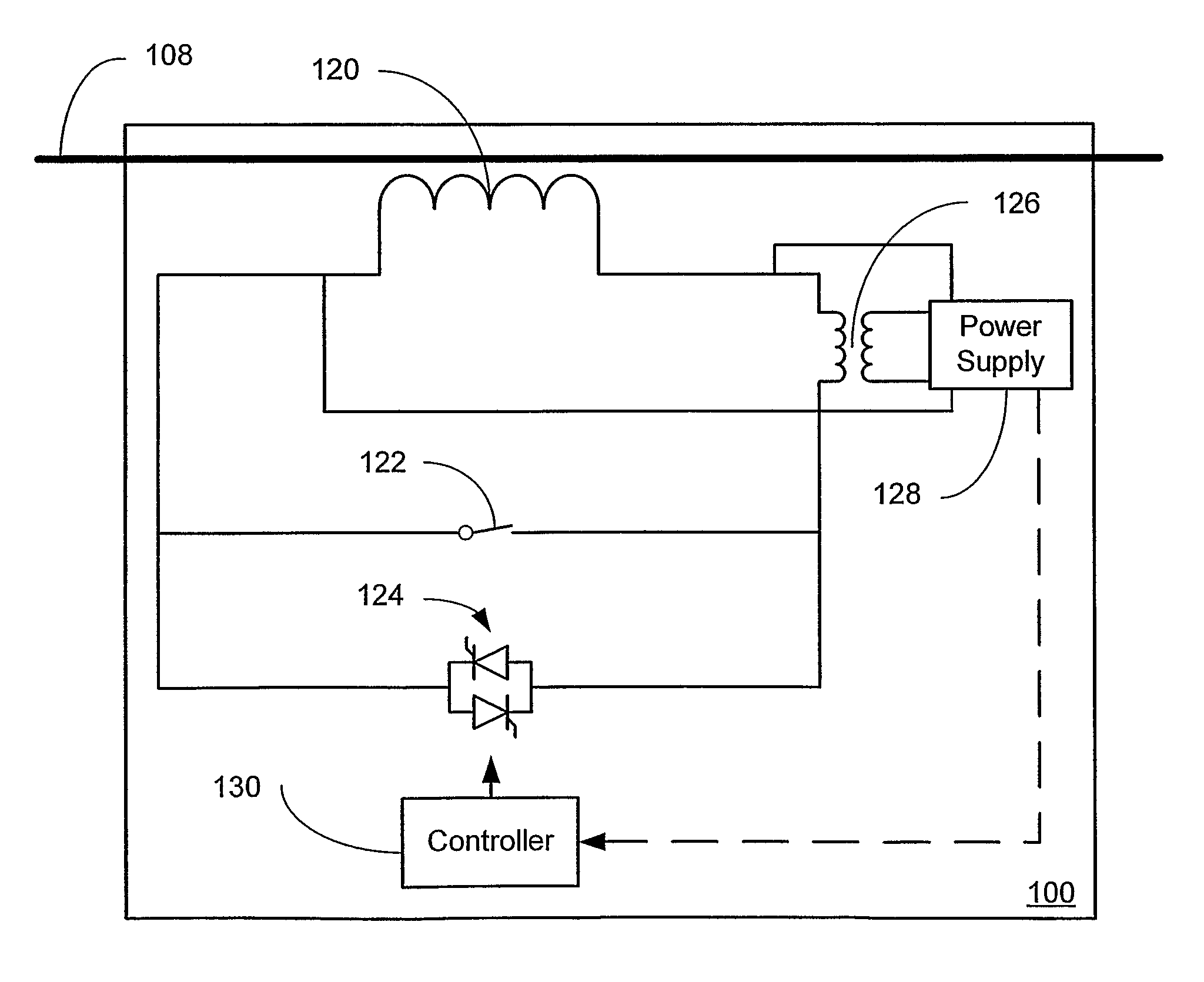
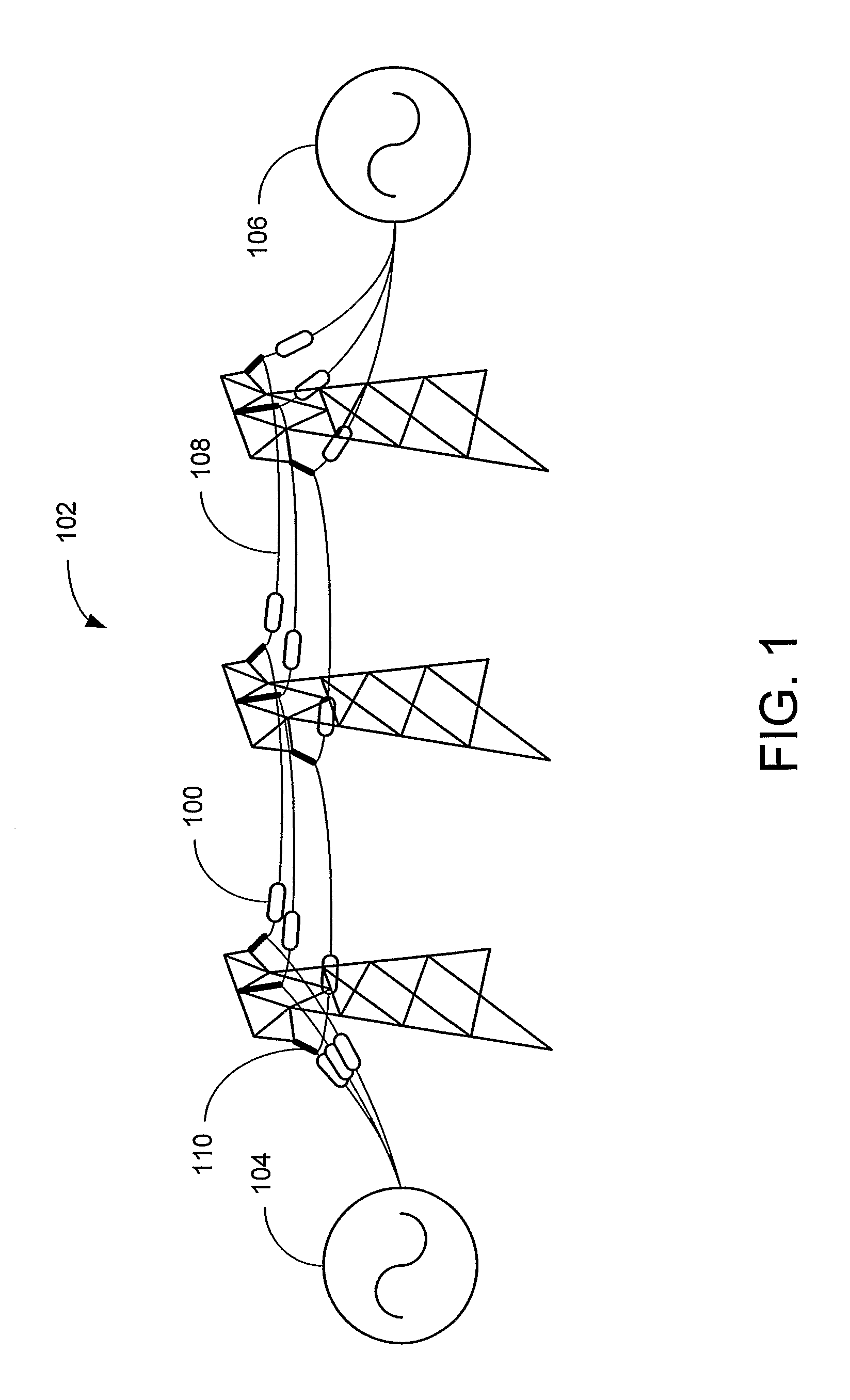
[0025]FIG. 1 illustrates an embodiment of a distributed series reactor (DSR), denoted by reference numeral 100, for line overload control by insertion of a distributed series impedance into a conductor 108 of an electric power system 102. The electric power system 102 has an electric power source 104 and a load 106 connected by at least one, and usually multiple, conductors 108. Of course, the electric power system 102 may have multiple power sources 104 and multiple loads 106. The DSR 100 is attached to a transmission line conductor 108 preferably, but not necessarily, near to an insulator 110. As discussed further below, the DSR 100 modules are formed to attach to the conductor 108 without requiring a break or any other physical modification to the power line. Further, the DSR 100 operates without the necessity of information regarding currents flowing in the rest of the network, without a central controller, and without a communication infrastructure that is normally required for...


PUM


Abstract

Systems and methods for implementing line overload control via providing distributed series impedance are disclosed. One system, amongst others, comprises at least one distributed series reactor (DSR). Each DSR comprises a single turn transformer (SST) comprising two split-core sections (132), a winding (120), and an air-gap (138), the air-gap designed such that a magnetizing inductance is produced when the two split-core sections (132) are clamped around a conductor (108). Each DSR further comprises a contact switch (122) that short circuits the winding when the contact switch (122) is in a closed condition, a power supply (128) that derives power from conductor line current, and a controller (130) configured to open the contact switch when the conductor line current reaches a predetermined value, thus causing insertion of the magnetizing inductance into the conductor. The controller (130) may be further configured to close the contact switch (122) when the conductor line current drops below the predetermined value.

Description

CROSS-REFERENCE TO RELATED APPLICATION[0001]This application claims priority to copending U.S. provisional application entitled, “Systems and Methods for Determining Power System Transmission Line Information”, having Ser. No. 60 / 648,466 filed Jan. 31, 2005, which is entirely incorporated herein by reference.TECHNICAL FIELD[0002]The present disclosure is generally related to controlling power flow in a transmission grid and, more particularly, to inserting distributed series impedance into power transmission lines to reduce the current flow in the targeted lines.BACKGROUND OF THE INVENTION[0003]Of the challenges facing utilities, a major issue is the elimination of transmission constraints and bottlenecks. A significant issue in terms of grid utilization is active power flow control. Electric utility customers purchase real power, megawatts and MW-Hrs, as opposed to voltage or reactive power. Thus, control of how and where real power flows on the network is of critical importance. C...

Claims


Application Information

Patent Timeline
Patent Type & Authority Patents(United States)
IPC IPC(8): H02H9/02
CPCH02J3/1807H02H9/02Y02E40/30
Inventor DIVAN, DEEPAKRAJ MALHARJOHAL, HARJEET
Owner GEORGIA TECH RES CORP
Why Eureka
Try Eureka