MR invasive device and method for active MR guidance of invasive devices with target navigation

a technology of invasive devices and target navigation, applied in the field of magnetic resonance imaging, can solve problems such as inaccurate representation of the true position of the device, device deviation from the scan plane of the roadmap, and possible misregistration errors of the map

Inactive Publication Date: 2010-11-16
LG CHEM LTD +1
View PDF11 Cites 15 Cited by
  • Summary
  • Abstract
  • Description
  • Claims
  • Application Information

AI Technical Summary

Problems solved by technology

However the static roadmap may contribute to misregistration error due to subject movement that is likely to occur, for example, in abdominal invasive procedures.
Moreover, when the invasive device trajectory is complex, such as in intravascular procedures, it is quite possible for the device to deviate from the roadmap scan plane.
Accordingly the simple overlay of a graphical marker on a static roadmap image can lead to an incorrect representation of the true position of the device.
However significant challenges exist in acquiring the t

Method used


Image

  • MR invasive device and method for active MR guidance of invasive devices with target navigation
  • MR invasive device and method for active MR guidance of invasive devices with target navigation
  • MR invasive device and method for active MR guidance of invasive devices with target navigation

Examples


second embodiment

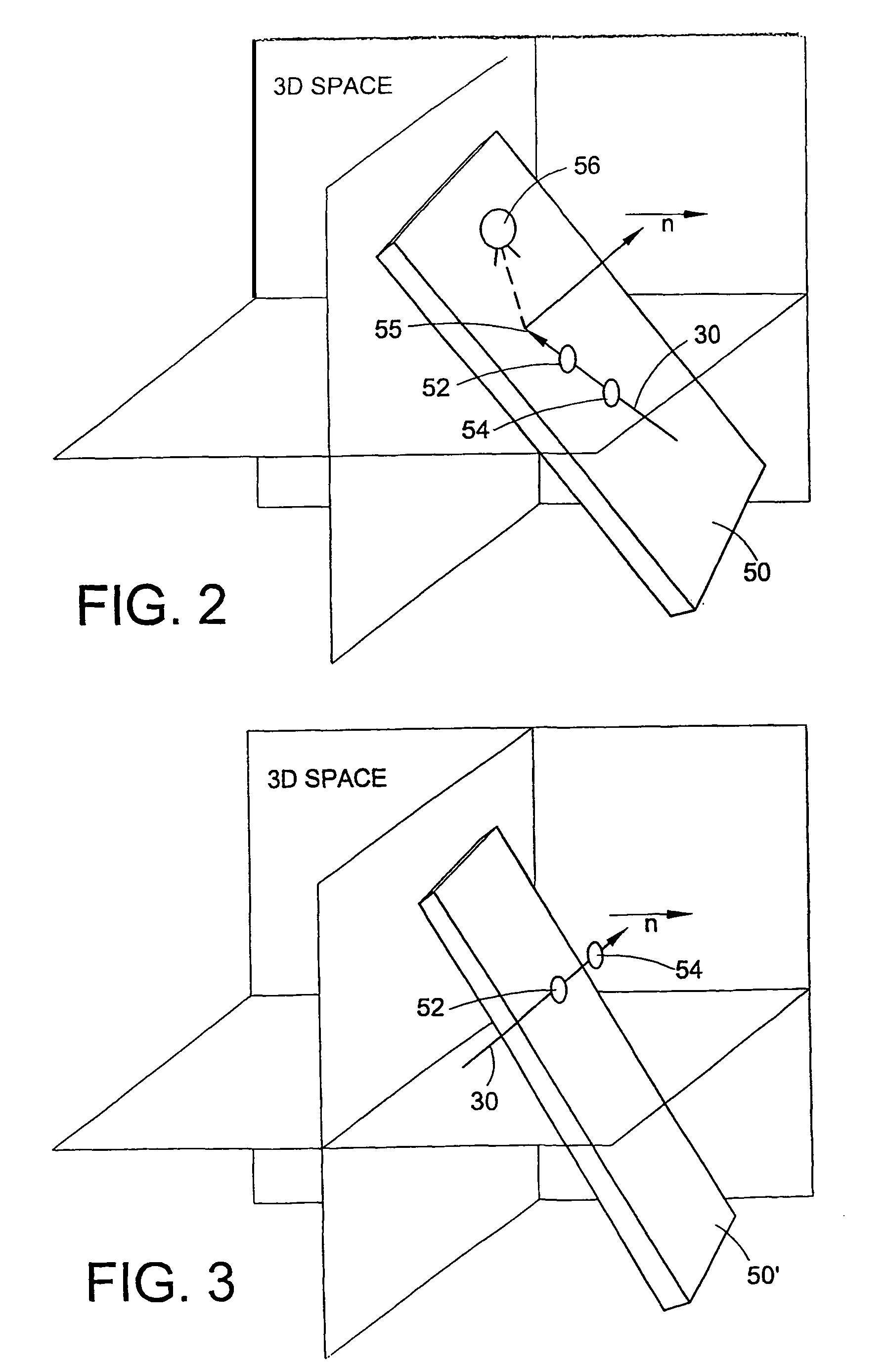
[0030]the scan plane is shown generally at 50′ in FIG. 3. The points 52, 54 on the device 30 are used to determine the orientation of the device. A plane can be defined by a point in the plane and a normal to the plane. The device 30, the orientation of which is determined by points 52, 54, is used as the normal, and the scan plane 50′ is defined by the orientation of the device 30 and one point 52 on the device. In this embodiment, the scan plane 50′ is perpendicular to the device 30.

first embodiment

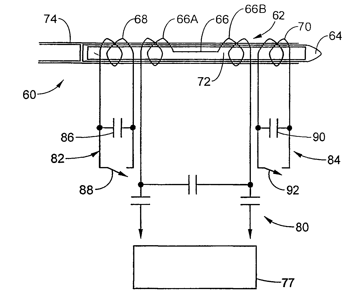
[0031]Referring now to FIG. 4, the invasive device 30, is a catheter shown generally at 60. Although a catheter 60 is discussed for the purposes of illustrating the invention, it should be appreciated that the invasive device 30 can also be a guide wire, an endoscope, a laparoscope, a biopsy needle, a surgical instrument or any other suitable known invasive device for use in an MR environment.

[0032]A 5F catheter was selected for use, although any suitably sized catheter may be used. The catheter 60 includes an inductive coupling structure 62, preferably disposed near the tip 64 at a distance from about 1 to 10 mm, although greater distances may be used. The inductive coupling structure may itself form the tip of the catheter when it is attached thereto. The inductive coupling structure 62 includes a first RF micro coil 66, a second RF micro coil 68 and third RF micro coil 70. The three micro coils are disposed in a spaced apart, coaxial relationship along the catheter 60. The micro ...


PUM


Abstract

An invasive device having an inductive coupling element. One embodiment of the invasive device includes a plurality of receive coils inductively coupled to a communicating coil. The receive coils are selectively tuned and detuned to receive MR signals for providing coordinate information used for device tracking. A second embodiment of the invasive device includes a receive coil having a plurality of winding elements separated from each other by different distances. A method of rapidly acquiring both the invasive device orientation and position information to dynamically adapt MR scan planes to continuously follow the invasive device relative to a target is provided. The target-navigation technique automatically defines the MR scan plane and a time domain multiplexing technique is applied for MR imaging and device tracking. Using these techniques, the acquired MR images shows both the invasive device and the target tissue.

Description

CROSS REFERENCE TO RELATED APPLICATIONS[0001]This application claims the benefit of U.S. Provisional Application No. 60 / 193,294, filed Mar. 30, 2000, which is hereby incorporated herein by reference.BACKGROUND OF THE INVENTION[0002]The present invention relates to magnetic resonance (MR) imaging. More particularly it relates to an improved invasive device capable of providing position and orientation information in an MR system. The invention further relates to a method of rapidly acquiring information on both the position and orientation of an invasive device to dynamically define MR scan planes for continuous tracking of the invasive device. The invasive device tracking information and dynamic MR imaging are used to show both the invasive device and the target to enhance target-navigation.[0003]In invasive MR guided procedures, reliable and accurate visualization of surgical and interventional instruments hereinafter referred to as invasive devices, inside the body of the subject ...

Claims


Application Information

Patent Timeline
IPC IPC(8): A61B5/05G01R33/28G01R33/34
CPCG01R33/287G01R33/34084
Inventor DUERK, JEFFREY L.ZHANG, QIANGWENDT, MICHAELCHUNG, YIU-CHOLEWIN, JONATHAN S.MERKLE, ELMAR M.
Owner LG CHEM LTD
Why Eureka
Try Eureka