Speed control of multiple components in refrigerant systems

a technology of refrigerant system and variable speed control, which is applied in the direction of cooling fluid circulation, lighting and heating apparatus, domestic cooling apparatus, etc., can solve the problems of complex circuitry, high cost of variable speed drives, and high cost of independent variable speed control and drives at each component that would desirably be run at a variable speed

Active Publication Date: 2010-11-23
CARRIER CORP
View PDF6 Cites 8 Cited by
  • Summary
  • Abstract
  • Description
  • Claims
  • Application Information

AI Technical Summary

Problems solved by technology

On the other hand, variable speed drives are expensive.
Having an independent variable speed control and drive at each component that would desirably be run at a variable speed would be very expensive.
Further, if plural variable speed drives are utilized, the circuitry becomes complex, and undue amounts of space are required.
Also, the variable speed controls may only be engaged during limited periods of time during unit operation.
However, it has not been known to utilize a variable speed drive that can be selectively connected between a compressor motor and a fan motor.

Method used


Image

  • Speed control of multiple components in refrigerant systems
  • Speed control of multiple components in refrigerant systems
  • Speed control of multiple components in refrigerant systems

Examples


Embodiment Construction

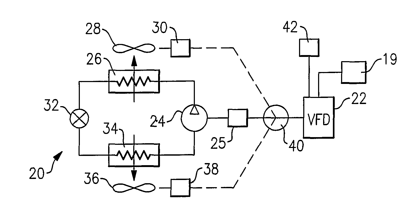
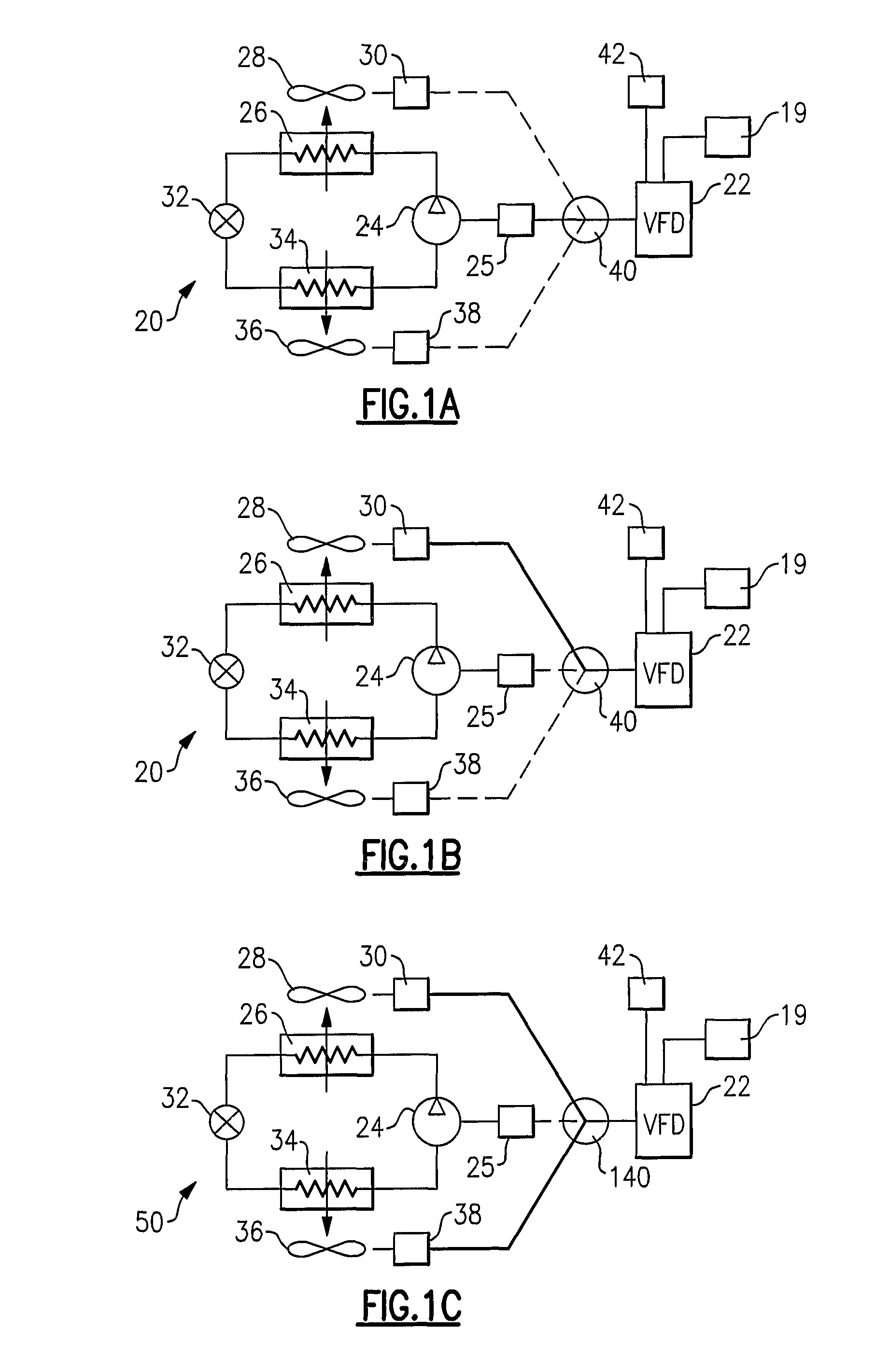
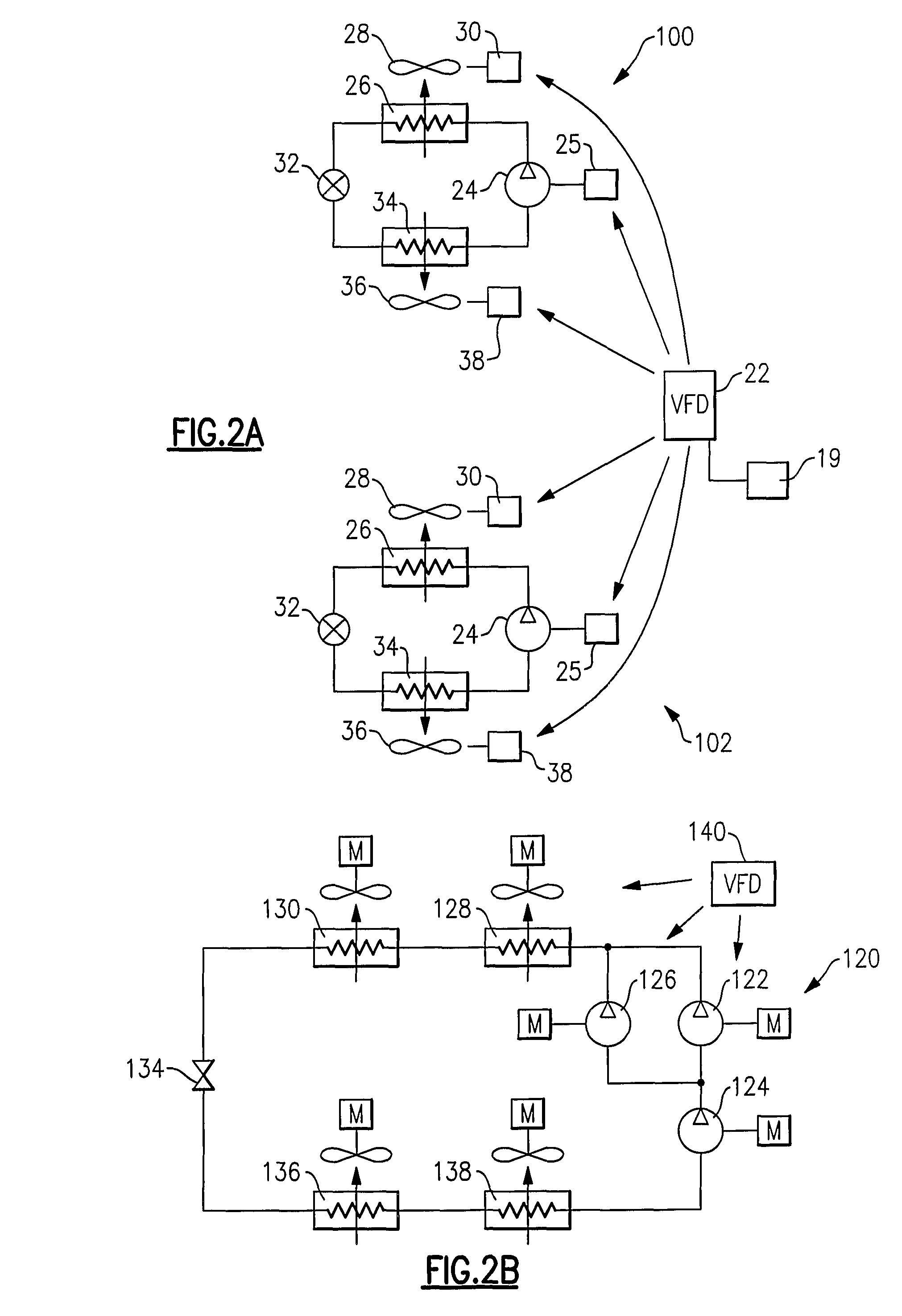
[0015]FIG. 1A shows a refrigerant system 20 incorporating a variable speed drive 22. As is known, a variable speed drive (or variable frequency drive “VFD”) provides a variable frequency to electric motors. A controller 19 provides control signals to the variable speed drive based upon system operating and environmental conditions. The controller 19 compares various system operating parameters, and the conditions required to be maintained in the space associated with the refrigerant system, and determines when a variable speed drive function for a motor associated with the refrigerant system 20 might become advantageous. This portion of the present invention is as known in the prior art.

[0016]As is known, a refrigerant system 20 typically includes a compressor 24 having a motor 25, and delivering a compressed refrigerant to a heat exchanger such as an outdoor heat exchanger 26. Also, as is known, a fan 28 having an electric motor 30 blows air over the heat exchanger 26. Downstream o...


PUM


Abstract

Variable speed drives are utilized in refrigerant systems to operate motors of the system components at varying speeds, typically for the purposes of capacity adjustment, efficiency enhancement, reliability improvement or power consumption limitation. However, variable speed controls are expensive. The present invention offers flexibility to utilize a variable speed drive to provide variable speed functionality between compressor and fans (or other rotating components having electric motors) within a refrigerant system depending on operational and environmental conditions and external load demands. The switching device switches the variable speed drive between component motors as indicated by a control for the refrigerant system.

Description

BACKGROUND OF THE INVENTION[0001]This application relates to a refrigerant system wherein a single variable speed control is selectively utilized to provide operation of different components within the refrigerant system at variable speeds.[0002]Refrigerant systems are utilized in applications to change the temperature and humidity or otherwise condition the environment. In a conventional refrigerant system, a compressor delivers a compressed refrigerant to a heat exchanger, known as a condenser, which is typically located outdoors. From the condenser, the refrigerant passes through an expansion device, and then to an indoor heat exchanger known as an evaporator. In the evaporator, moisture may be removed from the air, and the temperature of air blown over the evaporator coil is reduced. From the evaporator, the refrigerant returns to the compressor. Of course, basic refrigerant systems are utilized in combination with many other optional features and in various design configuration...

Claims


Application Information

Patent Timeline
Patent Type & Authority Patents(United States)
IPC IPC(8): F25D17/00F25B49/00
CPCF25B49/025F25B1/10F25B2400/06F25B2400/075F25B2600/021F25B2600/111F25B2600/112Y02B30/741Y02B30/743Y02B30/70
Inventor LIFSON, ALEXANDERTARAS, MICHAEL F.LORD, RICHARD
Owner CARRIER CORP
Why Eureka
Try Eureka