Method of determining the robustness of endformed tubular assembly and predicting the performance of such assembly in high pressure applications

a tubular assembly and robustness technology, applied in the field of fluid flow assemblies, can solve the problems of inefficiency of tube-o connectors, unreliable brazing connections, and unsatisfactory connections, so as to reduce the operating life of the assembly, prevent structural deformation of the clamp plate during use, and eliminate failure modes

Inactive Publication Date: 2010-11-23
YH AMERICA
View PDF33 Cites 0 Cited by
  • Summary
  • Abstract
  • Description
  • Claims
  • Application Information

AI Technical Summary

Benefits of technology

[0010]It is an object of the invention to provide a reliable, non-destructive method for determining the robustness of an endform tubular assembly having measurable structural elements formed therein.
[0011]It is another object of the invention to provide a reliable, non-destructive method for predicting the performance of the endform tubular assembly in high pressure applications for prolonged periods of time.
[0014]The endform tubular member has an inner surface and outer surface, the outer surface corresponding to the inner surface of the connector member securely locking the endform tubular member to the connector member. The endform tubular member includes a bead uniformly formed circumferentially around the outer surface of the endform tubular member adjacent the distal end of the first shoulder portion of the connector member. The bead fixedly engages the fixing member(s) in the first shoulder portion to prevent axial rotation of the endform tubular member relative to the first shoulder portion, and to further prevent longitudinal movement of the endform tubular member relative to the first shoulder portion. The bead also provides a first unique and important feature in the endform tubular assembly of the invention. A precise measurement of the diameter of the bead provides a quantifiable value for assessing the robustness of the endform tubular assembly and for predicting the performance of the endform tubular assembly in high pressure applications over prolonged periods of time.
[0015]The endform tubular assembly of the present invention is a robust design that is designed to eliminate failure modes associated with brazing and / or welding that can cause reduced operating life of the assembly; prevent structural deformation of the clamp plate during use; and prevent premature o-ring failure commonly found in conventional fluid-conveying tubular assemblies.
[0016]A particular advantage of the endform tubular assembly design of the present invention is that the assembly includes at least two inherent features that can be measured and the quantifiable values obtained can be used individually or in combination to assess the robustness of the endform tubular assembly, and predict the performance probability of the endform tubular assembly in high pressure applications.

Problems solved by technology

Tube-o connectors are considered to be inefficient since they require a separate installation step for each connection.
While the single torque bracket connection is effective for reducing the number of operational steps necessary in the assembling process, such connections are unsatisfactory because they generally require that at least one of the tubular members be brazed into a machined connector.
Brazed connections are not reliable, particularly in applications where the brazed part is subjected to the harsh environmental conditions present in the engine compartment of an automotive vehicle.
For example, the brazed part may be subjected to extremely cold temperatures in winter during periods when the automotive vehicle is not operating and then suddenly required to withstand high temperatures during operation of the automotive vehicle.
Constant vibrational episodes and occasional debris entering the compartment also severely reduce the life expectancy of such brazed connections.
Another disadvantage of prior brazed clamp plate connections is that the clamp plate does not sit flush against the housing, such that when torque is applied to the fastener, the bracket may distort leading to premature o-ring failure.
Such arrangements are not without disadvantages.
For example, such fluid flow assembly may employ undesirable brazing or welding for securing at least one of the supply hose and the return hose to the connector.
Such arrangement is not only time consuming and labor intensive, but the tube may be susceptible to undesirable axial rotation as well as up / down and side to side movement in the bracket.
Such undesirable movement severely limits the life expectancy of the assembly Furthermore, each of the return and pressure hoses require the additional step of forming a groove in the ends of the hoses for receiving an o-ring.
Consequentially, current tubular assembly design does not provide an economical fluid flow bundle having assured long term dependability and structural integrity, nor does it provide inherent features, which allow the reliable assessment of the robustness of such fluid flow assemblies.

Method used


Image

  • Method of determining the robustness of endformed tubular assembly and predicting the performance of such assembly in high pressure applications
  • Method of determining the robustness of endformed tubular assembly and predicting the performance of such assembly in high pressure applications
  • Method of determining the robustness of endformed tubular assembly and predicting the performance of such assembly in high pressure applications

Examples


first embodiment

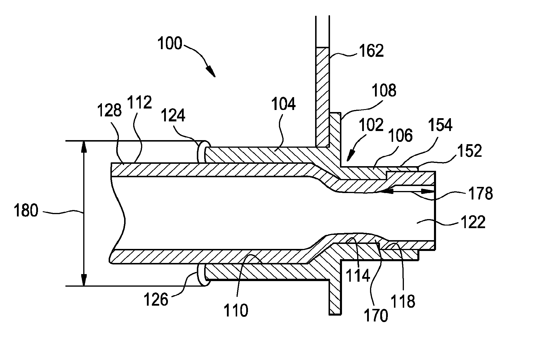
[0023]In the invention, one of at least two structural elements inherently formed in the endform tubular structure is a uniform bead circumferentially formed on the tubular member of the endform tubular structure adjacent the distal end of the connector member. The bead is measured to provide a reliable value for determining the robustness of the endform tubular assembly wherein the performance of the endform tubular assembly can be predicted in high pressure applications such as a power steering system, power brake system, air conditioner system, oil cooler system, various heating systems, and the like.

second embodiment

[0024]In the invention, one of at least two structural elements inherently formed in the endform tubular assembly is a cylindrical portion defined as a gauge diameter depth formed in the proximal of the endform tubular member. The longitudinal length of the gauge diameter depth is measured to provide a reliable value for determining the robustness of the endform tubular assembly wherein the performance of the endform tubular assembly can be predicted.

[0025]In accordance with the first embodiment of the invention, a method for endforming a tubular member to provide an endform tubular assembly for a hydraulic system comprises:

[0026](a) providing an endform tubular assembly comprising:[0027](1) a connector member comprising:[0028](i) a first shoulder portion, the first shoulder portion defining a distal end of the connector member, the first shoulder portion including at least one fixing member integral therewith; the first shoulder portion;[0029](ii) a second shoulder portion defining...


PUM


Abstract

A method is provided for determining the robustness of a tubular assembly in a fluid flow assembly for a hydraulic system and predicting the performance of the endform tubular assembly in high pressure applications, wherein the tubular assembly has inherent features therein that are measured to provide quantified values for assessing the robustness of the assembly and predict the performance of such assembly in high pressure applications for prolonged periods of time.

Description

BACKGROUND OF THE INVENTION[0001]1. Field of the Invention[0002]The present invention relates to fluid flow assemblies and, in particular, to tubular assemblies for the flow of fluid in hydraulic systems More particularly, the present invention relates to a method for determining the robustness of an endform tubular fluid flow assembly having measurable elements inherently formed therein and for predicting the performance of the endform tubular fluid flow assemblies in high pressure applications for prolonged periods of time.[0003]2. Discussion of Related Art[0004]Fluid flow assemblies for power steering systems include a steering gear housing, a steering gear disposed in the steering gear housing, a pump for moving the power steering fluid under pressure, a supply line for transporting pressurized fluid from the pump to the steering gear, and a return line for transporting the fluid from the steering gear back to the pump. Typically, such assemblies include one or more brackets or ...

Claims


Application Information

Patent Timeline
Patent Type & Authority Patents(United States)
IPC IPC(8): B07C5/00F16L39/00
CPCF16L41/001F16L41/082F16L2201/10
Inventor SKIBA, TERENCESTANLEY, RANDYLEMASTER, HERB
Owner YH AMERICA
Why Eureka
Try Eureka