
Wind deflector for motorcycle

a technology for wind deflectors and motorcycles, applied in cycle equipment, roofs, transportation and packaging, etc., can solve problems such as affecting the drag on the vehicle and the overall aerodynamics of the vehicl

Inactive Publication Date: 2010-11-23
SWENDER JAMES A
View PDF10 Cites 11 Cited by
  • Summary
  • Abstract
  • Description
  • Claims
  • Application Information

AI Technical Summary

Benefits of technology

[0007]Applicant's invention can be molded to fit the existing contours of the fairing of a motorcycle. The ability to attach the invention with adhesives also contributes to an aesthetically pleasing wind deflector. The shape of the invention then provides the operator greater relief from airflow pressure and objects carried in the air stream. The invention may be used in combination with existing factory-installed deflectors such as fairings and windshields to increase the vehicle's ability to reduce the amount of airflow impacting the operator.
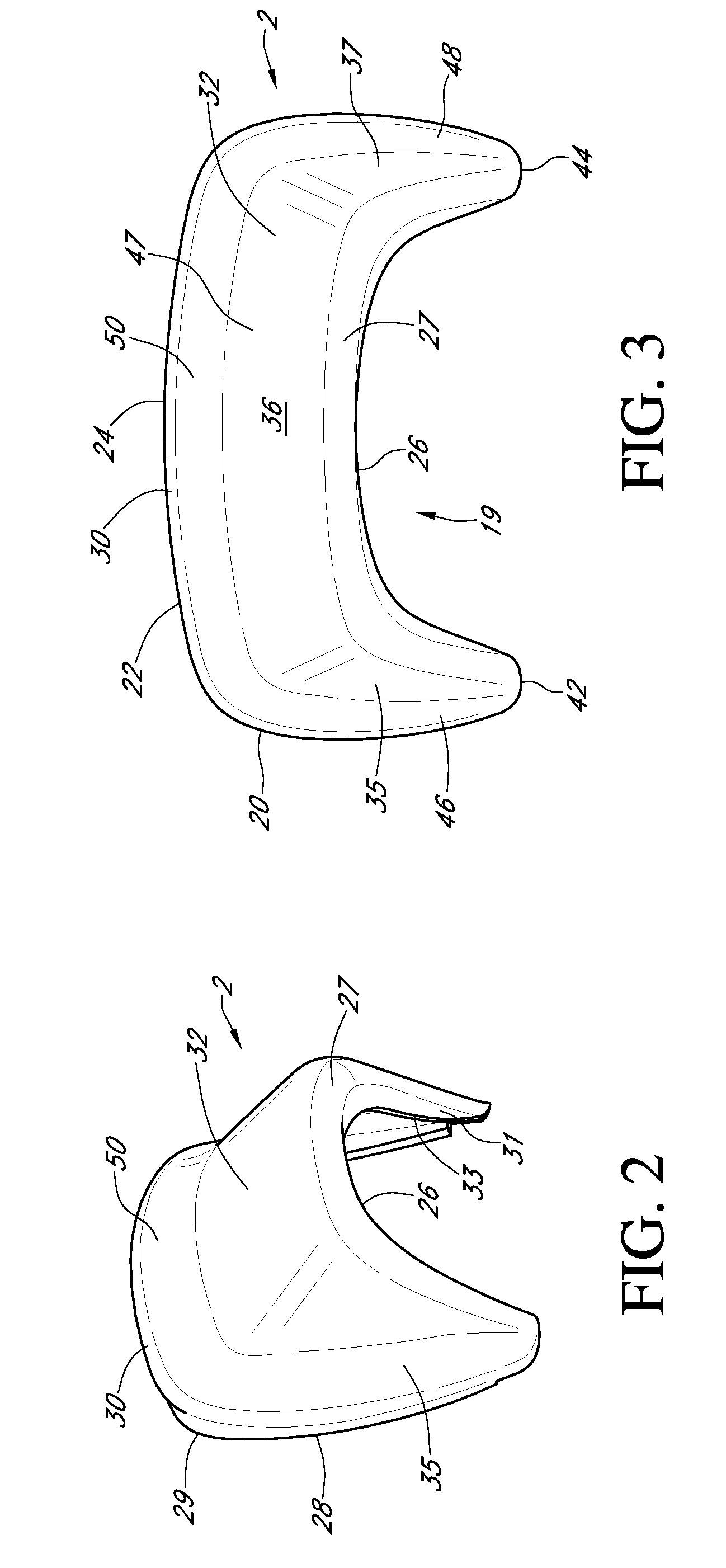
[0009]The invention reduces airflow on the operator of an open cockpit vehicle through the rear sloping protruding region and the concave region. The concave region is located on the upper portion of the invention. The slope of the concavity at its connection to the outer rounded edge affects the ability of the invention to deflect airflow away from the operator. In addition, the slope of the concave region affects the drag on the vehicle and the overall aerodynamics of the vehicle.
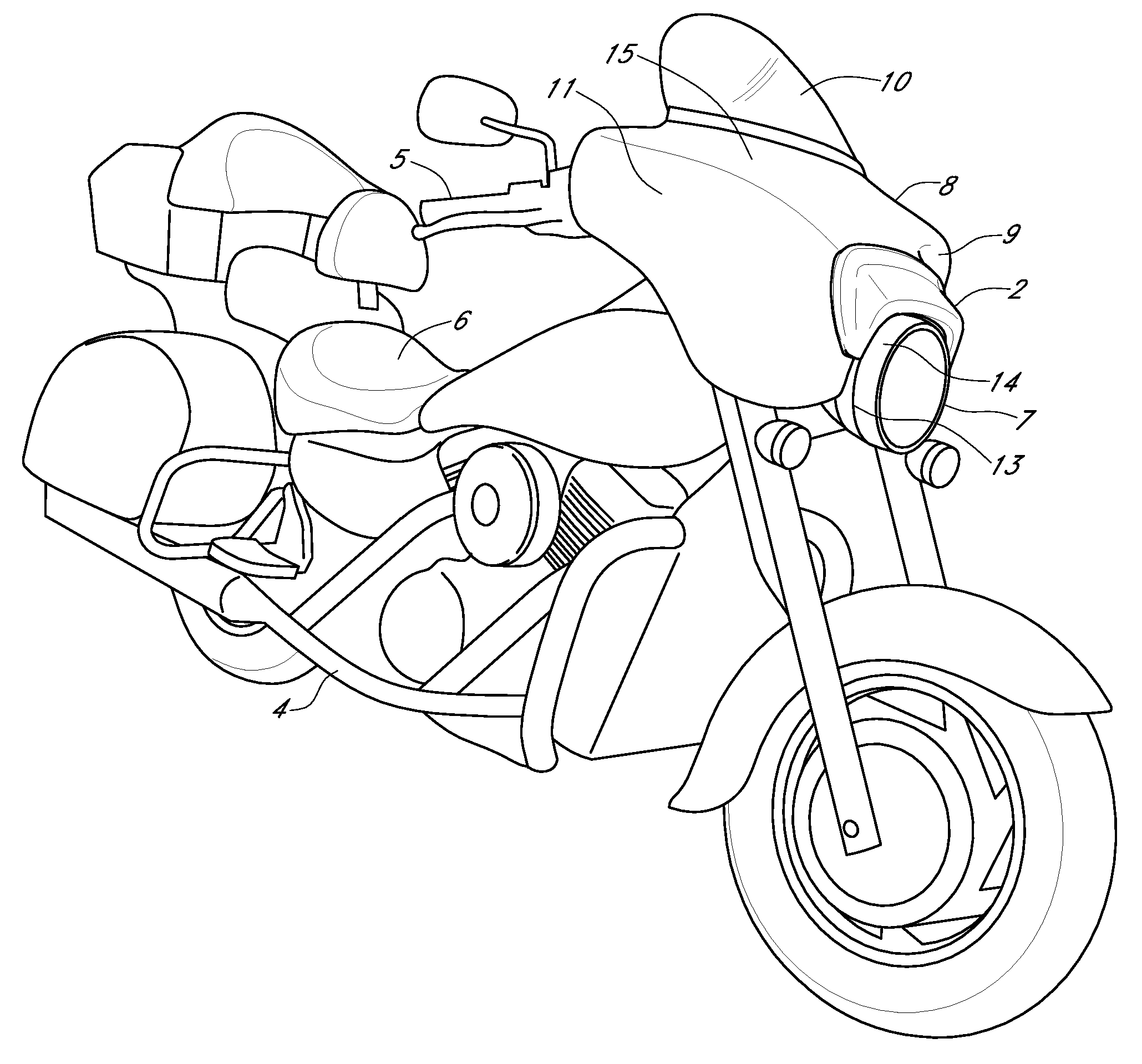
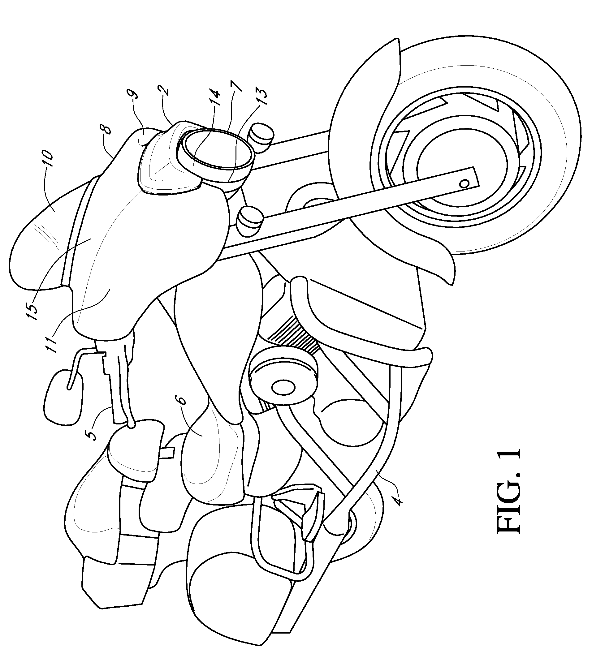
[0010]In the preferred embodiment, the invention is mounted to the fairing of the motorcycle just above the headlight. The invention cooperates with the fairing and the windshield to enhance the amount of airflow deflected away from the operator by the invention.
[0011]A primary object of the invention is to provide an improved wind deflector for a motorcycle which reduces the amount of airflow striking an operator while operating the vehicle.
[0013]A further object of the invention is to provide a wind deflector that is aesthetically pleasing in appearance. An additional object of the invention is to provide additional wind deflection for the operator of the motorcycle without modifying an existing fairing.

Problems solved by technology

In addition, the slope of the concave region affects the drag on the vehicle and the overall aerodynamics of the vehicle.

Method used


Image

  • Wind deflector for motorcycle
  • Wind deflector for motorcycle
  • Wind deflector for motorcycle

Examples


Embodiment Construction

[0023]Referring to the drawings and specifically to FIG. 1, the wind deflector 2 may be seen attached to fairing 8 of motorcycle 4. Motorcycle 4 contains the features of a typical open cockpit motorcycle including seat 6, handlebars 5 and headlight 7. Fairing 8 and windshield 10 provide the user partial protection from airflow and objects in the air stream while the motorcycle is operated on a roadway.

[0024]The wind deflector 2 is preferably mounted on the fairing 8 immediately above and partially surrounding the headlight 7. Specifically the wind deflector 2 is mounted over and adjacent to the upper part of cowling 14 of the headlight 7. Wind deflector 2 is approximately ten to twenty inches in width and five and a half inches to eleven and a half inches in overall height. Preferably wind deflector 2 is eleven to twelve inches in width and six to seven inches in overall height. Leading edge 27 of wind deflector 2 protrudes forward of fairing 8 approximately three to four inches and...


PUM


Abstract

A wind deflector for the front fairing of a motorcycle mounts to the fairing above the headlight. The wind deflector includes a deflection surface with a top region and side regions which slope upwardly and rearwardly from a rounded leading edge which stands off from the fairing. The deflection surface is joined to an arched rounded trailing edge by a shallow concavity. The trailing edge is above and behind the leading edge and also stands off from the fairing.

Description

BACKGROUND OF THE INVENTION[0001]Open cockpit vehicles such as motorcycles expose the operator to a variety of elements including airflow, rain, insects and dust. The flow of air impacts the user of the vehicle, especially at high speeds. This wind resistance may lead to the tiring of the operator as well as leaving the operator susceptible to impacts from insects and other objects in the air stream.[0002]Various deflectors, shields and fairings have been implemented to protect the operator from the forces associated with the operation of open cockpit vehicles. A common shield utilized for such protection is a transparent windshield attached to a part of the open cockpit vehicle. For a motorcycle, specifically, the windshield is typically fastened in some manner to a fairing which shields the torso of the motorcycle operator.[0003]Deflectors and shields may also be used in a variety of other places to relieve the forces of airflow on other portions of a motorcycle and the operator. ...

Claims


Application Information

Patent Timeline
Patent Type & Authority Patents(United States)
IPC IPC(8): B62J17/06
CPCB62J17/02B62J17/10
Inventor SWENDER, JAMES A.
Owner SWENDER JAMES A
Learn More