Seat suspension

a seat and suspension technology, applied in the field of seat suspension, can solve the problems of limiting the occupant's visibility of the area immediately in front of the boat, the cost of two bar mechanisms to fabricate and install in the seat, and the cost of assembly to the seat, etc., to achieve the effect of convenient service, quick, easily and inexpensively assembled, and convenient disassembly and assembly

Active Publication Date: 2010-11-23
MILSCO LLC
View PDF13 Cites 22 Cited by
  • Summary
  • Abstract
  • Description
  • Claims
  • Application Information

AI Technical Summary

Benefits of technology

[0044]It is an advantage of the present invention to provide a seat suspension arrangement where components, such as the webbing and any springs, can be replaced or otherwise easily serviced.
[0045]It is an advantage of the present invention to provide a seat suspension arrangement of multi-stage construction whose load-deflection characteristics can be tailored for a wide variety of applications, including for marine and off-road vehicle applications.
[0046]It is an advantage that a bolster arrangement made in accordance with the invention is provided with a positive lock in the up position that keeps it in the up position.
[0047]It is an advantage that a bolster arrangement made in accordance with the invention moves more freely between its up and down positions once disengaged from being locked in the up position.
[0048]It is an advantage of the present invention to provide a bolster arrangement that also can be quickly, easily and inexpensively assembled.
[0049]It is an advantage of the present invention to provide a bolster arrangement that also can be quickly and easily disassembled for servicing.

Problems solved by technology

When a watercraft is accelerating from slow speed operation to higher speed operation, the bow of the boat often rises significantly, temporarily restricting the occupant's visibility of the area immediately in front of the boat.
The two bar mechanisms are very costly to fabricate and to install in the seat.
In addition to the cost to fabricate the linkage mechanisms, assembly to the seat is also costly due to the large number of fasteners required.
Because the painted linkage arms are visible at each side of the bolster, overall appearance of the chair suffers because the arms cannot be color-matched to the vinyl in an effective manner.
Shortcomings of this construction include the cost and painting of the aluminum components and high assembly costs.
Another significant shortcoming of this design is that the hinge system does not provide a forward lock when the bolster is in the raised position.
The resulting change in position for the operator could lead to loss of control of the watercraft.
This protrusion limits the size of the seat pan and detracts from the overall comfort of the seat.
In addition, if an internal suspension is included in the seat pan, the limited space reduces the size and shock absorption capabilities of the suspension system.
Because the blow-molding process is not capable of producing parts with tight tolerance control, the force required to rotate the bolster from the lower to the raised position varies considerably as a result of wide variations in dimensions required by the process.
Another disadvantage of this construction is that the bolster component is difficult and costly to upholster due to its U shaped nature.
And, the U shape limits the styling possibilities for the seat as well.
Another significant shortcoming of this design is that this system does not provide a forward lock when the bolster is in the raised position.
The resulting change in position for the operator could lead to loss of control of the watercraft.
This requires considerable force and not all workers are capable of completing the task.

Method used


Image

  • Seat suspension
  • Seat suspension
  • Seat suspension

Examples


Embodiment Construction

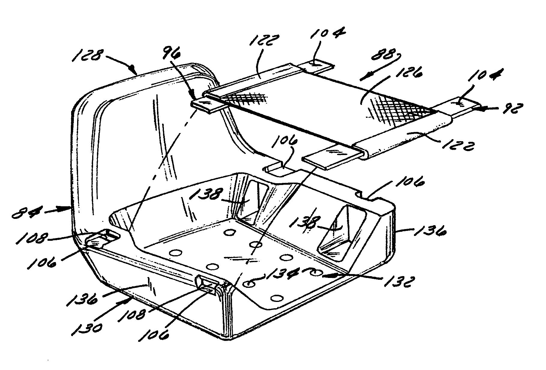
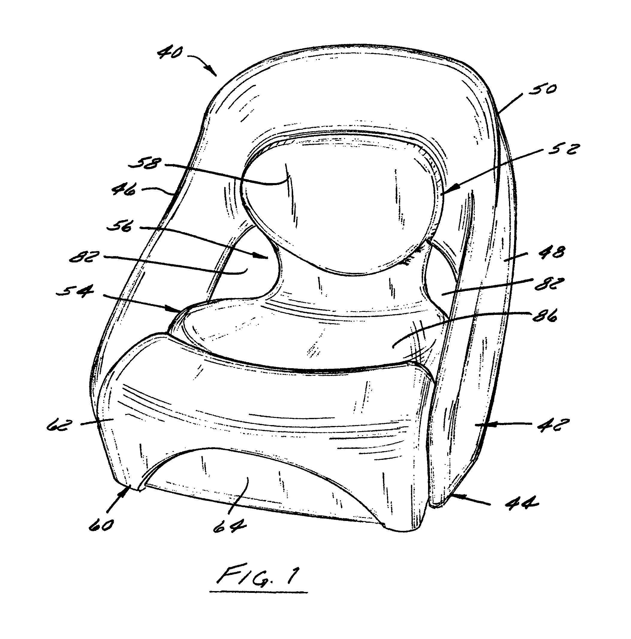
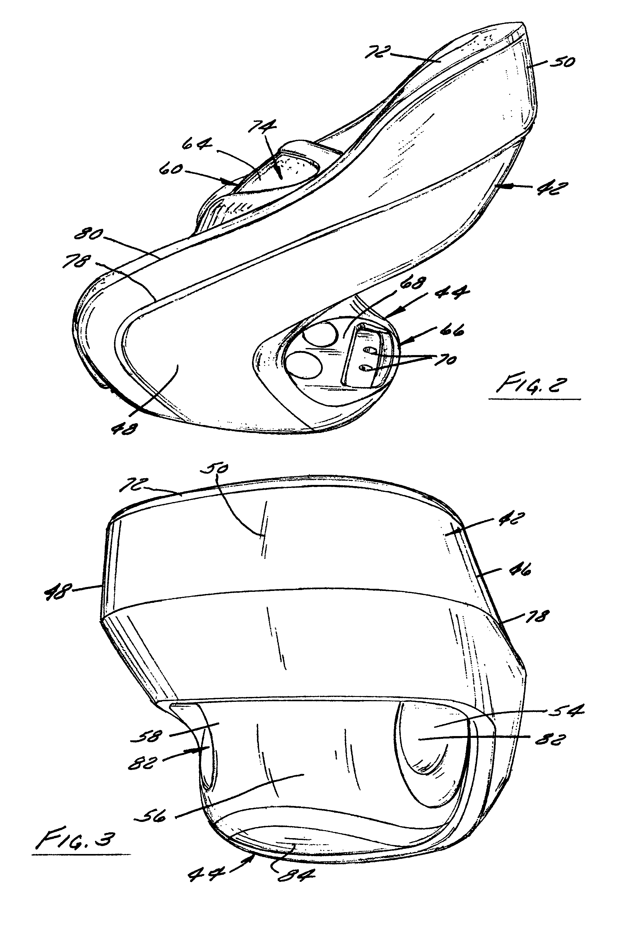
[0080]FIG. 1 illustrates one preferred embodiment of a seat, bolster and shell assembly 40 that is well suited, for example, for use in marine seating applications as well as other off-road vehicle seating applications. The shell 42 includes a base 44, a pair of sidewalls 46, 48 that extend generally upwardly from the base 44, and a back wall 50 that extends between the sidewalls 46, 48 and curls around the backside of a seat occupant (not shown). The seat 52 is removably received in the shell 42 and supported by the shell 42. The seat 52 has a cushion 54, a necked down portion 56, and a seat back 58 that supports one of the upper and lower lumbar portion of the back of a seat occupant. The bolster 60 is shown in a down position with its seat cushion surface 62 disposed forwardly of the cushion 54 of the seat 52. The bolster 60 has a second seat occupant supporting surface 64 that is shown in a forwardly facing position. When needed, the bolster 60 can be moved from its down positio...


PUM


Abstract

A seat suspension that includes at least one beam spring that extends across a seat pan. In one preferred embodiment, a pair of such springs is carried by the pan. The springs preferably differ in compliance from one another and from a mesh load supporting grid that is connected to each spring. One such arrangement produces a suspension of progressive construction that enables the seat to handle a wide range of shocks, bumps, jolts, and vibration of varying frequencies and magnitudes.

Description

CROSS REFERENCE TO RELATED APPLICATION[0001]This application is a divisional of U.S. application Ser. No. 10 / 922,053 Aug. 19, 2004 now U.S. Pat. No. 7,523,988, which claims the benefit under 35 U.S.C. §119(e) of U.S. Provisional Application Ser. No. 60 / 497,582, filed Aug. 25, 2003, the entirety of which is expressly incorporated by reference herein.FIELD OF THE INVENTION[0002]This invention primarily relates to a seat suspension, and more particularly to a mesh or fabric seat suspension.BACKGROUND OF THE INVENTION[0003]Vehicle seats in recreational watercraft have included flip up bolster systems for a number of years. Typically, flip up bolster systems involve having the forward edge of the seating surface (bolster) as a separate part from the rear portion of the seating surface. This forward portion of the seat complete with padding, upholstery and a structural core is connected to the remainder of the seat with a hinging system or mechanical linkage that enables the forward porti...

Claims


Application Information

Patent Timeline
Patent Type & Authority Patents(United States)
IPC IPC(8): A47C7/02
CPCB60N2/24B60N2/7011B63B29/04B63B2029/043
Inventor RATZA, CLIFTON J.EEKHOFF, TRENT A.
Owner MILSCO LLC
Why Eureka
Try Eureka