Magnetic head having oxidized read sensor edges to reduce sensor current shunting

a read sensor and magnetic head technology, applied in the field of magnetic read sensor edges, can solve the problems of reducing reducing affecting so as to reduce the shunting of electrical current, reduce the shunting of current, and improve the efficiency of read sensor

Inactive Publication Date: 2010-11-23
WESTERN DIGITAL TECH INC
View PDF22 Cites 5 Cited by
  • Summary
  • Abstract
  • Description
  • Claims
  • Application Information

AI Technical Summary

Benefits of technology

[0017]It is an advantage of the magnetic head of the present invention that damaged regions which do not contribute to the functioning of the sensor are made non-conductive so that shunting of current is reduced.
[0020]It is a further advantage of the magnetic head of the present invention that efficiency of read sensors is improved by reduction of electrical current shunting in damaged regions.
[0021]It is a yet further advantage of the magnetic head of the present invention that potential signal improvement of read sensors is obtained by reduction of electrical current shunting in damaged regions.

Problems solved by technology

During the milling and lapping operations, the magnetic material that makes up certain layers of the sensor typically becomes damaged at any or all of these four edges.
As a result, portions of the sensor near these edges may become magnetically inactive.
However, as read heads become smaller and smaller in size, these damaged areas become a larger proportion of the overall sensor head area.
In both CIP and CPP configurations, damage occurs to edge regions of the read sensor during fabrication processes used to produce the final dimensions of the read sensor.

Method used


Image

  • Magnetic head having oxidized read sensor edges to reduce sensor current shunting
  • Magnetic head having oxidized read sensor edges to reduce sensor current shunting
  • Magnetic head having oxidized read sensor edges to reduce sensor current shunting

Examples


Embodiment Construction

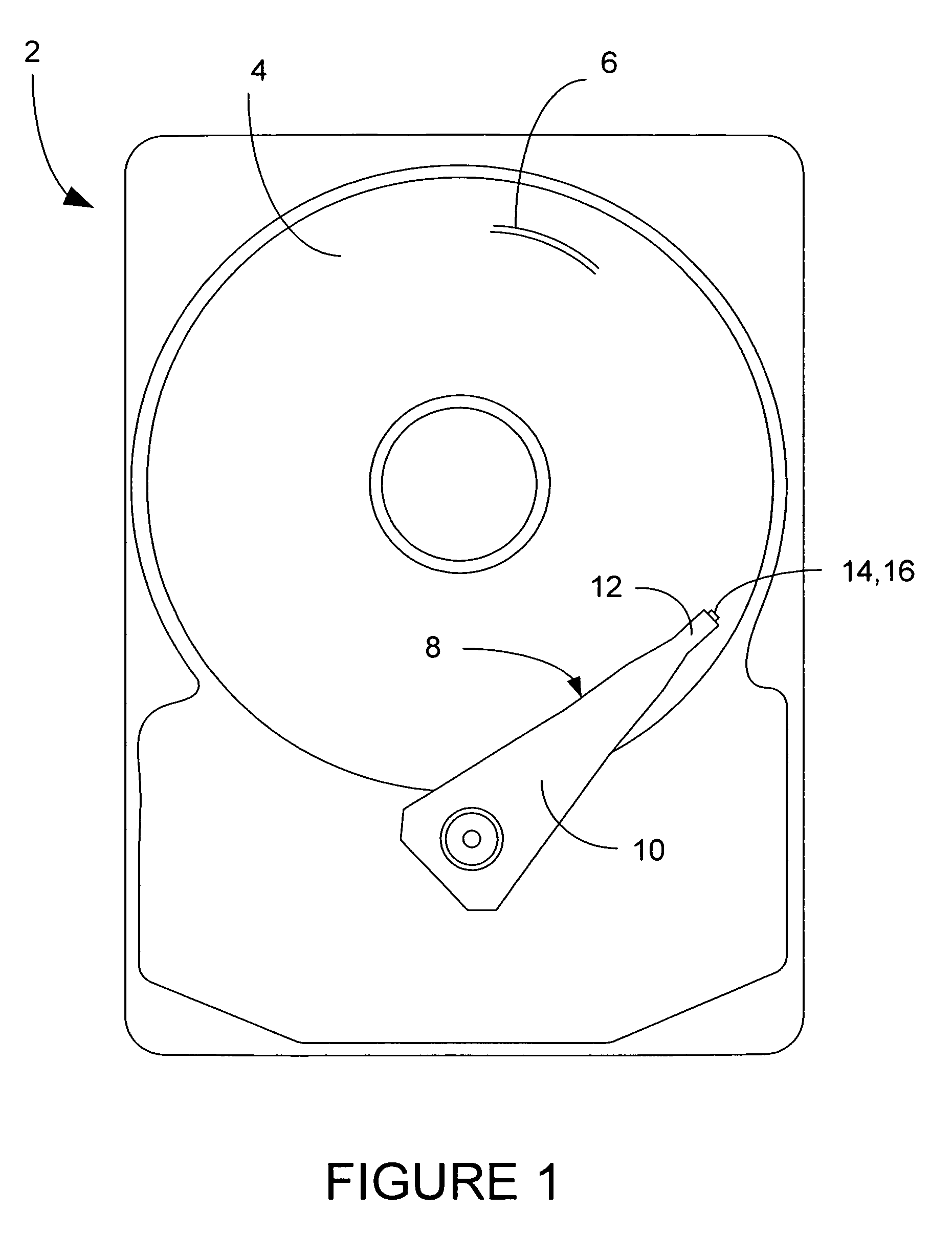
[0035]A magnetic disk drive 2 is shown generally in FIG. 1, having one or more magnetic data storage disks 4, with data tracks 6 which are written and read by a data read / write device 8. The data read / write device 8 includes an actuator arm 10, and a suspension 12 which supports one or more magnetic heads 14 included in one or more sliders 16.

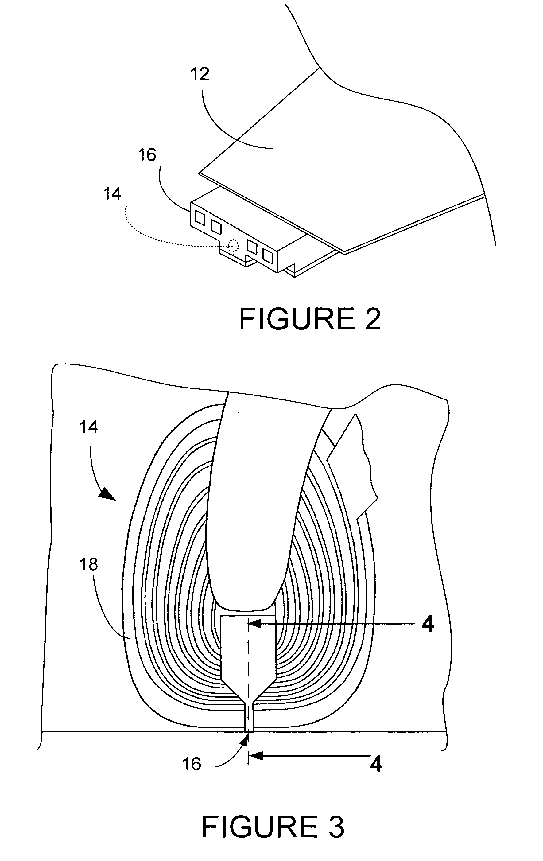
[0036]FIG. 2 shows a slider 16 in more detail being supported by suspension 12. The magnetic head 14 is shown in dashed lines, and in more detail in FIGS. 3 and 4.

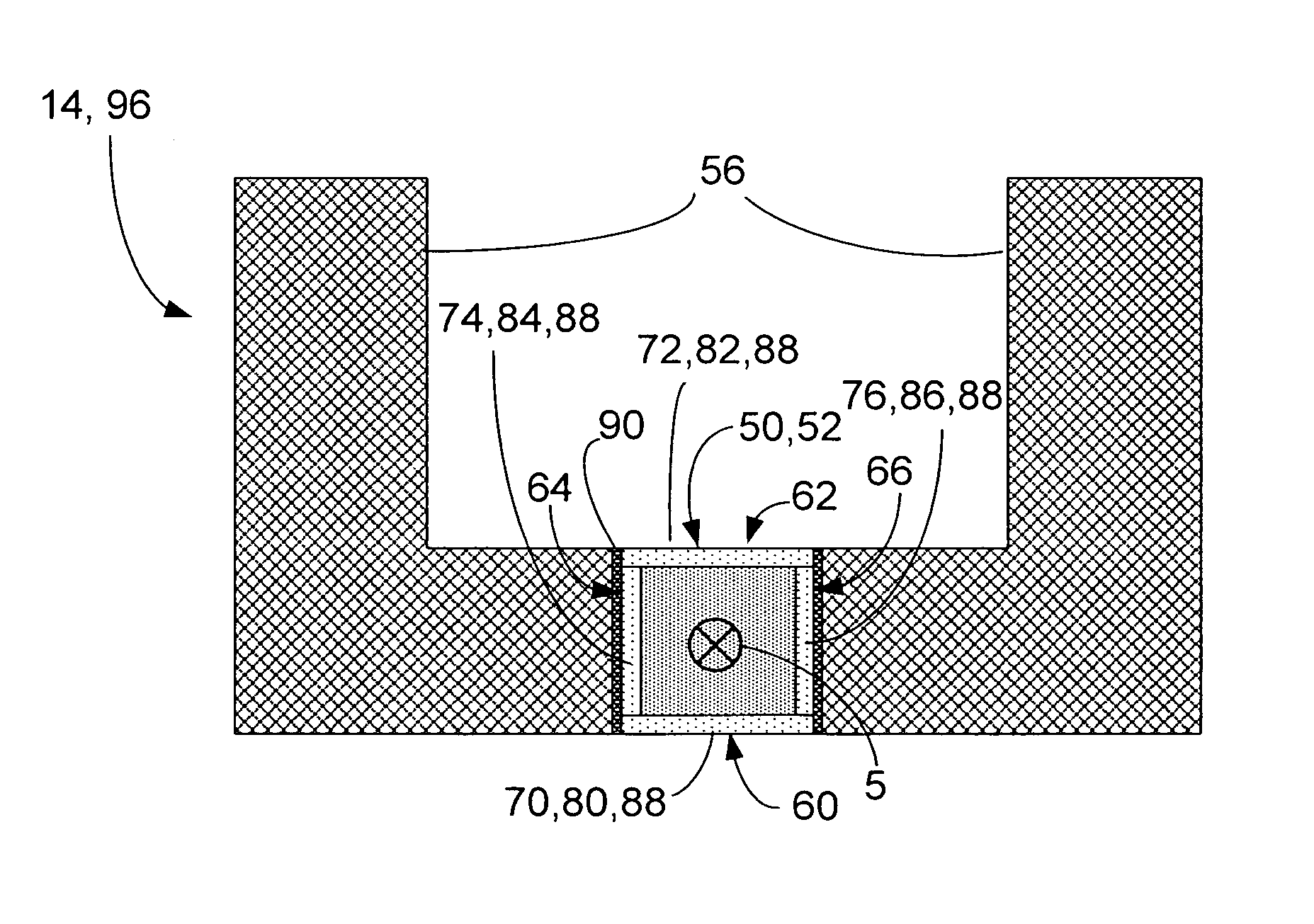
[0037]There are two configurations of read head in common use in the industry today. These are called Current In the Plane (CIP) and Current Perpendicular to the Plane (CPP), where the plane of reference is that of the layers of sensor stack material. The magnetic head 14 shown in FIG. 4 has a read head of a configuration known as Current In the Plane (CIP) 40 in which the current flows through the sensor perpendicularly in and out of the plane of the paper in the pictured figure rath...


PUM

PropertyMeasurementUnit
widthaaaaaaaaaa
non-conductive aaaaaaaaaa
widthaaaaaaaaaa

Abstract

A magnetic read head of either CIP or CPP configuration is disclosed having a read sensor having oxidized non-conductive regions. The read sensor has a front edge, a rear edge, a left-side edge and a right-side edge. For a CIP configuration, the front edge and the rear edge are oxidized to form non-conductive regions. For a CPP configuration, the left-side edge, the right-side edge, the front edge and the rear edge are oxidized to form non-conductive regions. Also disclosed are a disk drive including a read sensor having oxidized non-conductive regions, and a method of fabrication for a read sensor having oxidized non-conductive regions.

Description

BACKGROUND OF THE INVENTION[0001]1. Field of the Invention[0002]The present invention relates generally to magnetic heads for reading data written to storage media, and more particularly to magnetic read heads for disk drives.[0003]2. Description of the Prior Art[0004]A computer disk drive stores and retrieves data by positioning a magnetic read / write head over a rotating magnetic data storage disk. The head, or heads, which are typically arranged in stacks, read from or write data to concentric data tracks defined on surface of the disks which are also typically arranged in stacks. The heads are included in structures called “sliders” onto which the read / write sensors of the magnetic head are fabricated. The slider flies above the surface of the disks on a thin cushion of air, and the surface of the slider which faces the disks is called an Air Bearing Surface (ABS).[0005]The goal in recent years is to increase the amount of data that can be stored on each hard disk. If data tracks...

Claims


Application Information

Patent Timeline
Patent Type & Authority Patents(United States)
IPC IPC(8): G11B5/33
CPCB82Y25/00G01R33/093G11B5/3929G11B5/398
Inventor JAYASEKARA, WIPUL PEMSIRI
Owner WESTERN DIGITAL TECH INC
Why Eureka
Try Eureka