
Soil separating systems

a technology of soil separation and separating systems, applied in the field of soil separation systems, can solve the problems of affecting requiring several pieces of machinery and a great deal of manpower, and separating debris and rock from soil is a very expensive and time-consuming task, and it is difficult to achieve the effect of reducing the risk of accidents, and reducing the safety of horses

Inactive Publication Date: 2010-11-30
CHAVEZ JOSEPH J +1
View PDF7 Cites 21 Cited by
  • Summary
  • Abstract
  • Description
  • Claims
  • Application Information

AI Technical Summary

Benefits of technology

"The present invention provides a soil separating system that can efficiently and effectively separate unprocessed soil into selected and unselected materials. The system includes a separator that can separate the soil based on its particle size, an unprocessed soil collector for collecting the unselected soil onto the separator, a housing vehicle for housing the separator, a soil pusher for pushing the unprocessed soil over the separator, and a screen for screening the unselected soil from the selected soil. The system can also be adjusted for different particle sizes and can be powered by a hydraulic power system. The technical effects of the invention include improved efficiency, cost-effectiveness, and handiness of the system."

Problems solved by technology

Typically, separating debris and rock from soil is a very costly and time-consuming task requiring several pieces of machinery and a great deal of manpower.
For example, horse racetracks have an ongoing issue of maintaining rock free material to protect the horse and rider.
Flying rocks during competition have blinded many riders and horses.
The above-described tasks currently require using multiple pieces of equipment and considerable manpower that are both time-consuming and expensive.
The current method usually takes about one month or longer, during which time the track is generally unusable.

Method used


Image

  • Soil separating systems
  • Soil separating systems
  • Soil separating systems

Examples


Embodiment Construction

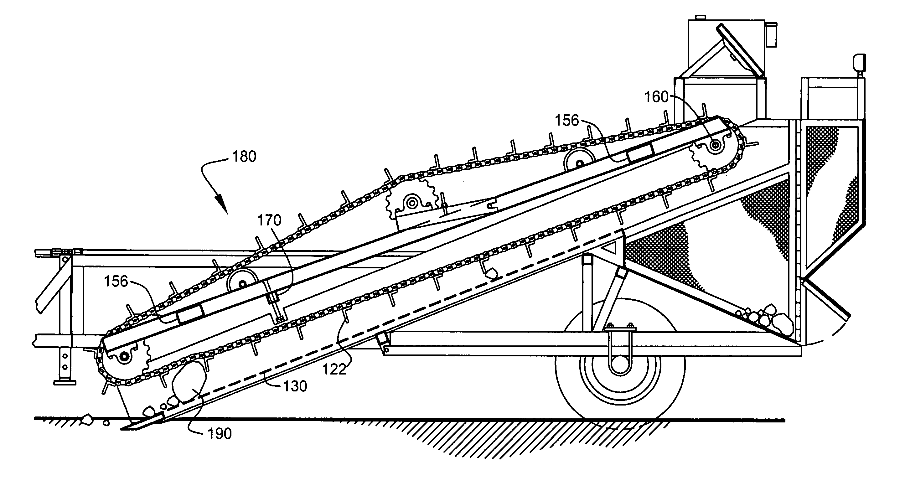
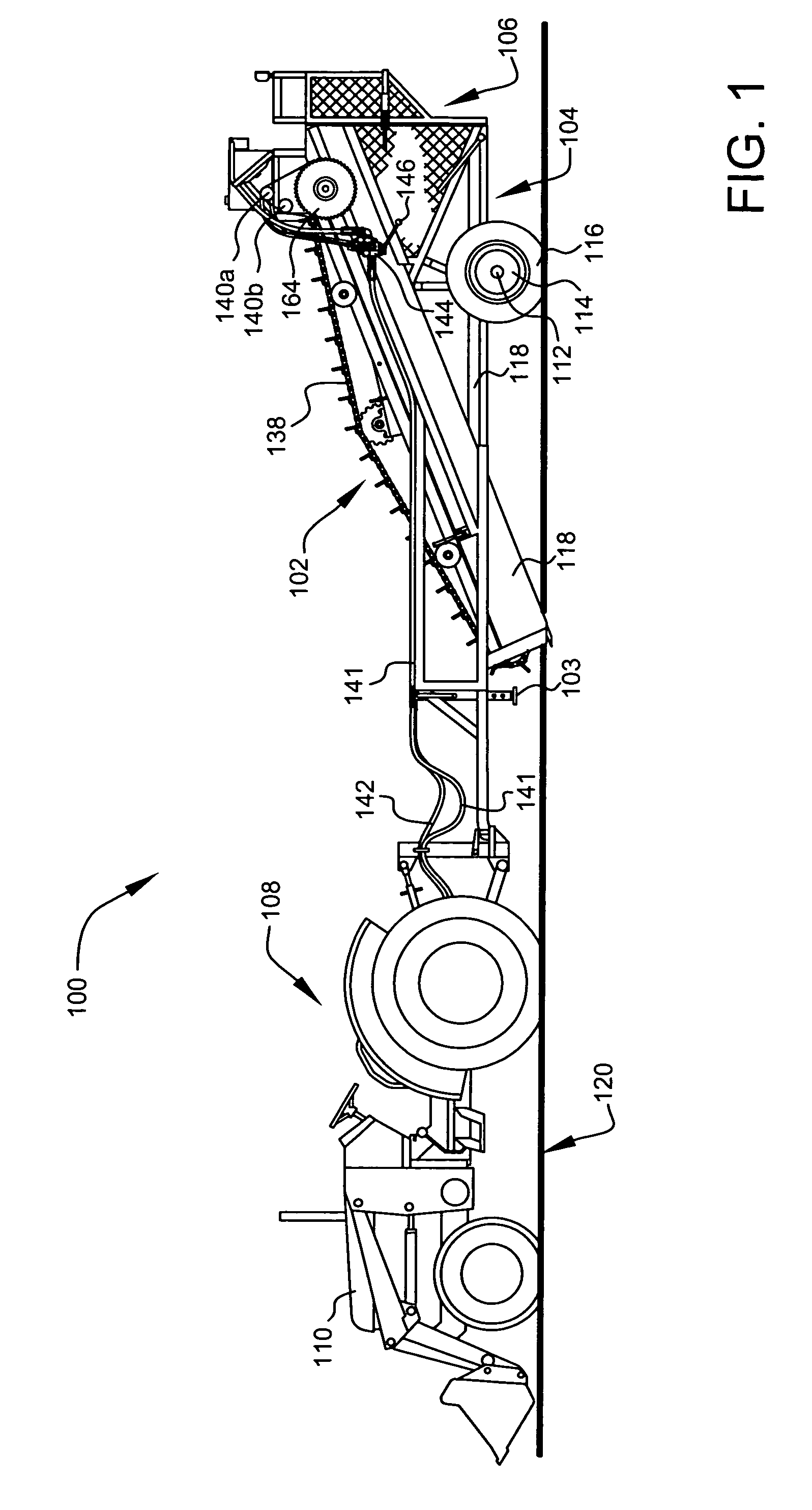
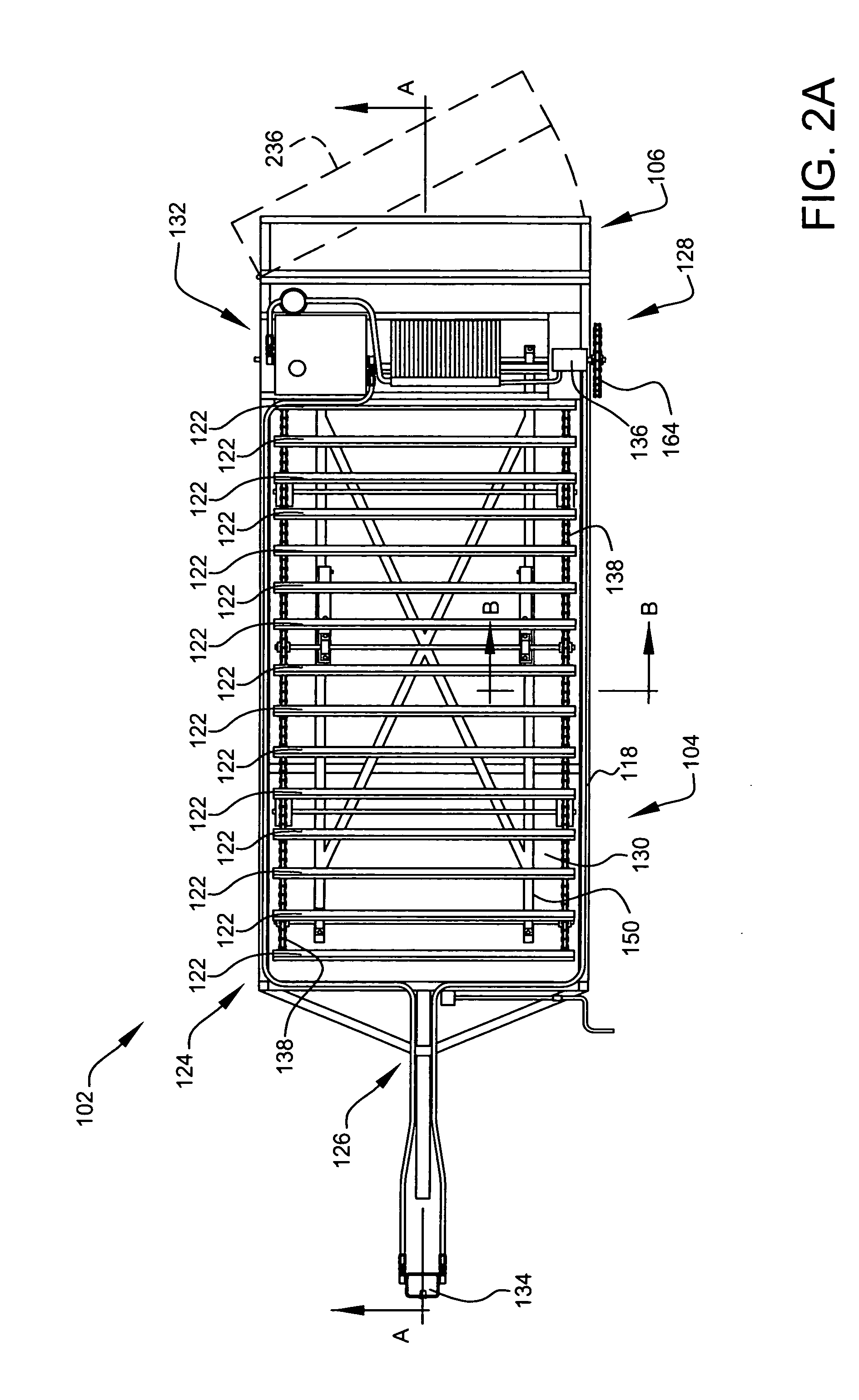
[0037]FIG. 1 shows a perspective view illustrating a soil separating system 100 according to a preferred embodiment of the present invention. Preferably, soil separating system 100 comprises a soil separator 102, a mobile housing assembly 104, and a discard bin 106, as shown. Preferably, soil separating system 100 further comprises a towing vehicle 108, as shown.

[0038]Preferably, mobile housing assembly 104 houses soil separator 102 and discard bin 106, as shown. Preferably, mobile housing assembly 104 is attachable to towing vehicles 108, as shown, most preferably both to a tractor 110 during operation and at least about a one-ton pick-up truck for over-the-road transport. Preferably, the combined weight of the mobile housing assembly 104, soil separator 102, and discard bin 106 is about 5000 pounds or less. Upon reading the teachings of this specification, those with ordinary skill in the art will now understand that, under appropriate circumstances, considering such issues as adv...


PUM


Abstract

A towable apparatus adapted for the separation of rock, stones, or debris from topsoil, having a stationary, non-vibrating sifting screen. A hydraulically powered conveyor belt with paddles pushes the soil across the sifting screen. The system provides features to assist prevention of machine jamming by large debris. A method of use is also disclosed.

Description

CROSS-REFERENCE TO RELATED APPLICATION[0001]The present application is related to and claims priority from prior provisional application Ser. No. 60 / 561,711, filed Apr. 12, 2004, entitled “RID O ROC”, and is related to and claims priority from prior provisional application Ser. No. 60 / 638,724, filed Dec. 23, 2004, entitled “SOIL SEPARATING SYSTEMS”, the contents of both of which are incorporated herein by this reference and are not admitted to be prior art with respect to the present invention by the mention in this cross-reference section.BACKGROUND[0002]This invention relates to soil separating systems. More specifically, this invention relates to providing a mobile system for improved soil separating of rock, stones and debris from topsoil.[0003]Typically, separating debris and rock from soil is a very costly and time-consuming task requiring several pieces of machinery and a great deal of manpower. For example, horse racetracks have an ongoing issue of maintaining rock free mate...

Claims


Application Information

Patent Timeline
Patent Type & Authority Patents(United States)
IPC IPC(8): A01B43/00
CPCA01B43/00
Inventor CHAVEZ, JOSEPH J.FARNSWORTH, CECIL C.
Owner CHAVEZ JOSEPH J
Learn More