Eureka AIR delivers breakthrough ideas for toughest innovation challenges, trusted by R&D personnel around the world.

Engineered composite wooden crib for use as a mine support

a composite, wooden crib technology, applied in the field of mining, can solve the problems of reducing the resistance of air flow through the crib, unable to allow large roof or floor rock movements, and significant deformation resistance, so as to achieve less wood, higher overall rigidity or rigidity, and less load

Inactive Publication Date: 2010-11-30
SOUTHERN ILLINOIS UNIVERSITY
View PDF14 Cites 3 Cited by
  • Summary
  • Abstract
  • Description
  • Claims
  • Application Information

AI Technical Summary

Benefits of technology

[0014]There are several distinct advantages of the engineered composite wooden crib element as compared to the current solid prismatic wooden crib element. First, since approximately two-thirds of the load-bearing portion of the element is loaded with the wood grain in the axial direction, it is capable of carrying significantly higher loads prior to failure. Laboratory experiments have indicated load carrying capacity to be 200% of the current practice. Second, since the elastic modulus in the axial direction is much higher then the parallel direction, the element has much higher overall stiffness or rigidity. Therefore, it does not allow large roof or floor rock movements prior to developing significant deformation resistance. Third, a 30-inch long engineered composite wooden crib element, as an example, uses about 25% less wood as compared to a typical solid wood prismatic crib element with the same overall dimensions. Larger elements lead to more significant material savings ratios. Therefore, the engineered composite wooden crib element is lighter overall and uses less wood material. The engineered composite wooden crib element is thus easier to carry and assemble in cribs, material costs are reduced, and fewer trees need be harvested to supply the mine with cribbing material. Fourth, because the engineered composite wooden crib element uses less material, it can be assembled in such a way as to reduce the cross-sectional area of the crib and thus significantly reduce resistance to air flow through the crib. This helps with methane removal and other reasons air flow is induced in mines. Fifth, since each crib assembled from engineered composite wooden crib elements can carry more load than typical solid wood element cribs, fewer cribs may be required.
[0015]In the example configuration previously mentioned, a 1.70″-by-5.75″-by-30″ center elongate element board, connecting the approximately cubical, rectangular prismatic, or disc-shaped outer plate contact blocks, has more than adequate strength to carry tensile and bending stresses. Furthermore, it is convenient and effective to use the center elongate element to lift the engineered composite wooden crib element during the crib construction process. The 1.70″-by-5.75″-by-30″ center elongate element board is loaded perpendicular to the grain which would normally yield at a low strength level of 500-700 psi. Since it is squeezed between two pieces of wood that have low Poisson's ratio and it is further vertically and horizontally reinforced by nails, bolts, screws, or other fasteners, or horizontal resistive forces offered by adhesives, or both, the overall board can carry much higher vertical loads prior to yielding or failure. The center board does provide some deformation or yielding behavior within the crib, however. Furthermore, the geometry of the contact area zone in the outer plate element for the engineered composite crib element can be readily changed by changing the size of the wooden pieces connected to a 5.75″-by-1.7″-by-30″ wooden piece. For example, the contact area could be made 5.75″-by-7″ or 5.75″-by-5.75″ or 5.75″-by-8″ depending upon the load carrying requirements and lateral stability requirements of the crib. The larger the contact area, the larger would be the load carrying capacity and the lateral stability of the crib structure.
[0016]Disadvantages with current crib use can also be overcome if the wedges used for tightening crib elements are: 1) wide and cover the entire area of the contact points, 2) relatively flat so that upon tightening they maintain contact over a large area (preferably over the entire contact area of the prismatic crib element) throughout loading to minimize stress concentrations and localized yielding, and 3) rigid or of high elastic modulus so that they provide large amount of preload for small horizontal displacement of the wedge. These conditions are easily met if 1) wooden wedges are cut so that loading is axial to the wood grain, 2) width of the wedges is the same as or larger than the size of the prismatic element, 3) two mating wedges are used, and 4) wedges are relatively thick (1-2 inches) with very low slope, or incline, angle. For example, based on wood axial elastic modulus of about 250,000 psi, only 0.5 inches horizontal displacement of a wedge with 0.1 degree slope angle will provide about 200 psi of preload. That translates to 3.5 tons of preload on one contact area of a 5.75 inch×5.75 inch crib element, or 14 tons of preload on the crib with four contact points. Similar analyses may be used to design wedges for the entire crib to achieve desired preload.

Problems solved by technology

Therefore, it does not allow large roof or floor rock movements prior to developing significant deformation resistance.
Fourth, because the engineered composite wooden crib element uses less material, it can be assembled in such a way as to reduce the cross-sectional area of the crib and thus significantly reduce resistance to air flow through the crib.

Method used


Image

  • Engineered composite wooden crib for use as a mine support
  • Engineered composite wooden crib for use as a mine support
  • Engineered composite wooden crib for use as a mine support

Examples


Embodiment Construction

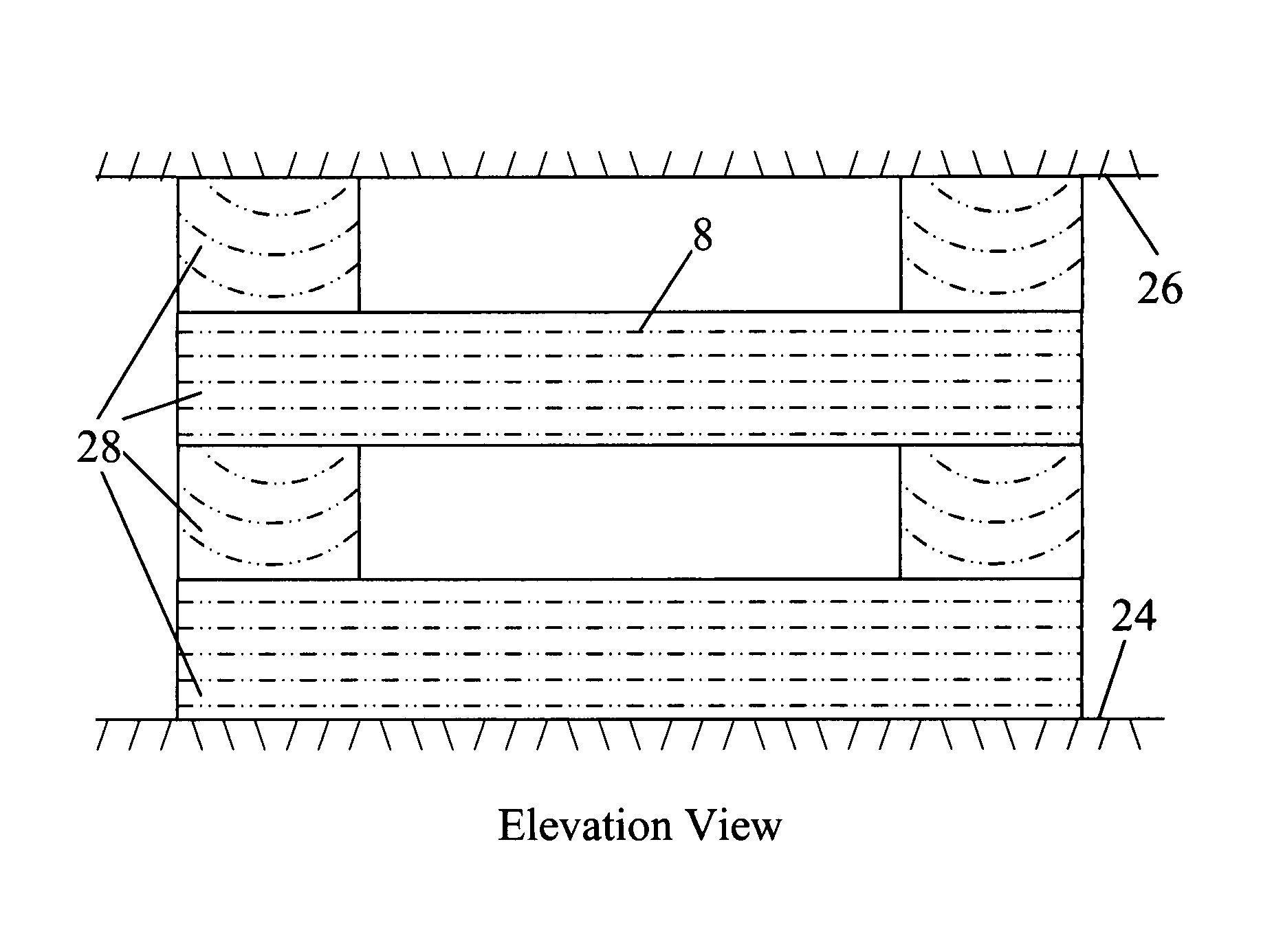
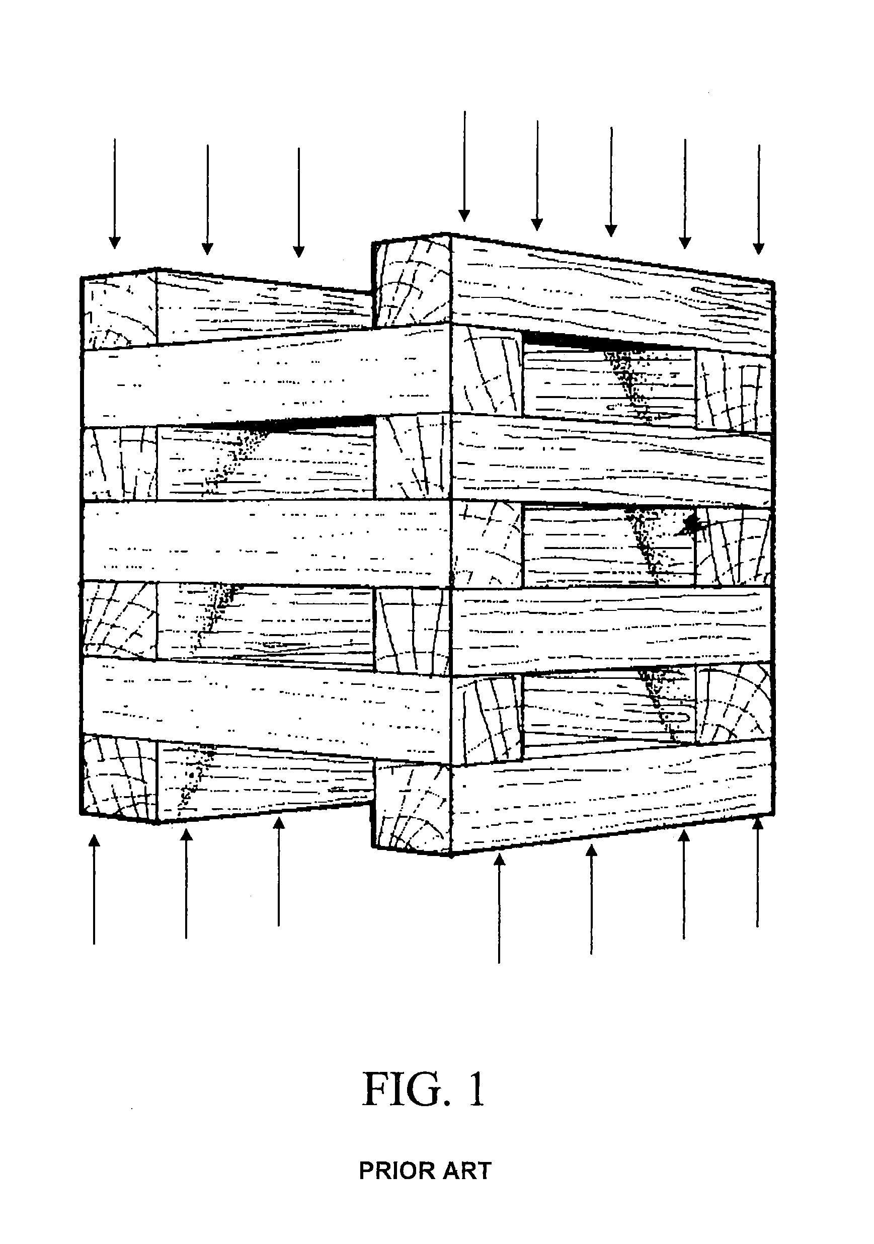
[0038]Referring to the drawings, the invention will be explained in further detail. In FIG. 1, a traditional solid wood element crib is shown. This figure shows a 7-layer crib in a 2 by 2 configuration, with each element parallel to the floor or roof surfaces, and with vertical force lines applied to the crib from the direction of the roof and floor. FIG. 7 shows an elevation view of a four-layer 2 by 2 crib using traditional solid wood elements 28, placed on the floor 24 and stacked up to the roof 26, and showing wood grain direction 8 in each element.

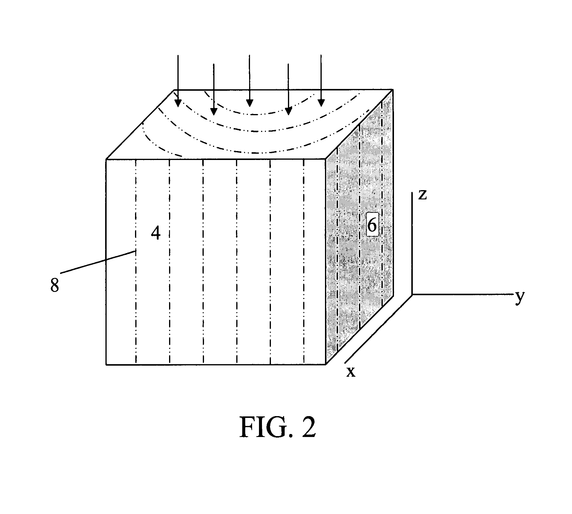
[0039]FIG. 2 shows a drawing of the loading direction in a solid wood element as is used in the typical crib element contained in the crib in FIG. 1. The force is applied to face 10 and is transverse to the grain direction 8 shown in FIG. 2. Face 12 shows the end grain of the block of wood. In this drawing, load is applied along axis y, and the grain runs along axis z. FIG. 11 shows a stress-strain graph of forces along the y axis in ...


PUM


Abstract

This invention provides improvements through 1) a composite, engineered wooden support element for construction of cribs in mines to provide support between two surfaces, 2) use of support elements to construct cribs, and 3) a wedge system to provide substantial sustained preload on a crib. The wooden support element consists of a center elongate element wherein the wood grain runs transversely to the crib element loading direction, and at least two outer plate elements wherein the wood grain runs axially with the crib element loading direction. Each outer plate element is attached to a surface of the center elongate element using fastening means and the outer plate element wood grain direction is aligned transversely to the grain direction in the center elongate element. The crib structure may be constructed by superimposing only these support elements in 2×2 layers or in conjunction with solid prismatic wooden elements. A wooden wedge system with relatively low angle surface and with wood grain running axially is utilized to apply vertical preload. Due to high stiffness of the wedge in the axial direction, a substantial vertical preload can be applied and sustained to make cribbing structure a more efficient load carrying structure. The wooden support elements are lightweight, have controllable higher stiffness and load carrying capacity than current cribs, engineered yielding characteristics and allow much lower resistance to air flow in underground mine roadways.

Description

FIELD OF INVENTION[0001]The invention relates primarily to mining, and more specifically to wooden cribbing for the support of hanging wall and foot wall, roof and floor, or upper and lower surfaces in underground mining, and secondarily to the temporary support of heavy structures such as houses or buildings being relocated or receiving foundation work.BACKGROUND OF INVENTION[0002]Wooden posts and wooden cribs, or chocks, are probably the oldest support systems used in the mining industry. A wooden post, typically 4 inches to 10 inches in diameter or square cross-section, loaded axially provides support between two points. A wooden crib or chock provides support over a larger area, typically varying from a 30 to 72 inches square. Wooden posts and wooden cribs are extensively used in the mining industry even today.[0003]A wood crib consists of layers of two or more parallel timbers with adjoining layers placed at right angles to each other, as shown in FIG. 1. Thus, the number of pa...

Claims


Application Information

Patent Timeline
Patent Type & Authority Patents(United States)
IPC IPC(8): E21D15/00
CPCE21D15/02
Inventor CHUGH, YOGINDER PAUL
Owner SOUTHERN ILLINOIS UNIVERSITY
Why Eureka
Eureka Blog
Learn More