
Energy absorber and method for manufacturing the same

a technology of energy absorbers and absorbers, which is applied in the direction of shock absorbers, elastic dampers, bumpers, etc., can solve the problems of increasing the weight of energy absorbers, interlayer cracks, and complex structure of fibers, so as to prevent the compressive load required for crushing, increase the amount of absorbed energy, and absorb energy stably

Active Publication Date: 2010-11-30
TOYOTA IND CORP
View PDF32 Cites 14 Cited by
  • Summary
  • Abstract
  • Description
  • Claims
  • Application Information

AI Technical Summary

Benefits of technology

[0009]Accordingly, it is an objective of the present invention to provide an energy absorber that prevents compressive load required for crushing from increasing at an early stage of crushing, stably absorbs energy, and increases the amount of absorbed energy. Another objective of the present invention is to provide a method for easily manufacturing the above energy absorber.
[0010]Further, it is an objective of the present invention to provide an energy absorber that increases the energy absorption power with a several percent of weight increase or less compared to a conventional energy absorber using a two-dimensional laminated fiber structure.
[0011]It is also an objective of the present invention to provide an energy absorber that prevents reaction force of the energy absorber from increasing at an early stage of crushing without using a two or more types of reinforcing fibers, and increases the energy absorption amount.

Problems solved by technology

Using metal for energy absorbers increases the weight.
This structure complicates the arrangement of the fibers.
When a force is applied to a two-dimensional laminated fiber structure along a direction perpendicular to its thickness, cracks are formed in a center portion along the thickness, which creates interlayer cracks.
This hampers the energy absorber from exerting the advantages of reinforcing fibers.
However, since a plurality of types fibers need to be prepared, the manufacture is troublesome.
Further, no measures are taken against a rapid progress of cracks between adjacent fiber layers.

Method used


Image

  • Energy absorber and method for manufacturing the same
  • Energy absorber and method for manufacturing the same
  • Energy absorber and method for manufacturing the same

Examples


first embodiment

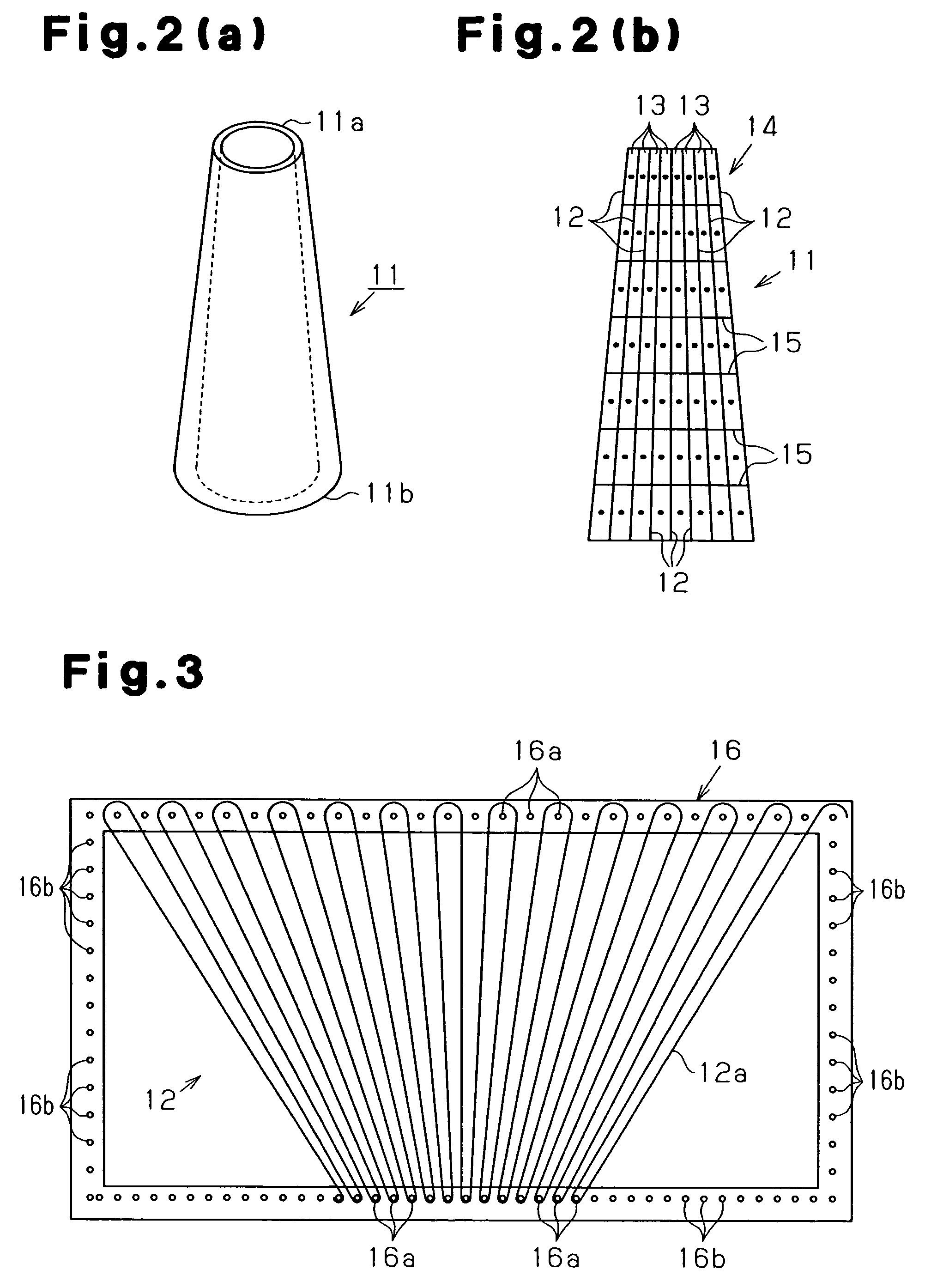
[0056]the present invention will now be described. As shown in FIG. 2(a), an energy absorber 11 is substantially cylindrical. As shown in FIG. 2(b), the energy absorber 11 is made of fiber-reinforced resin. The thickness of the energy absorber 11 varies from an upper end (distal end 11a) to a lower end (proximal end 11b). In other word, the thickness of the energy absorber 11 varies from a first end (distal end 11a) to a second end (proximal end 11b) of a compression direction of the energy absorber 11. The thickness of the energy absorber 11 is reduced from the proximal end 11b to the distal end 11a. The compression direction of the energy absorber 11 refers to a direction along which the energy absorber 11 receives compressive load when in use. In this embodiment, the energy absorber 11 receives compressive load from the distal end 11a along a vertical direction in FIG. 2(a). The base (proximal end 11b) of the energy absorber 11 is fixed to a predetermined position when in use. Th...

third embodiment

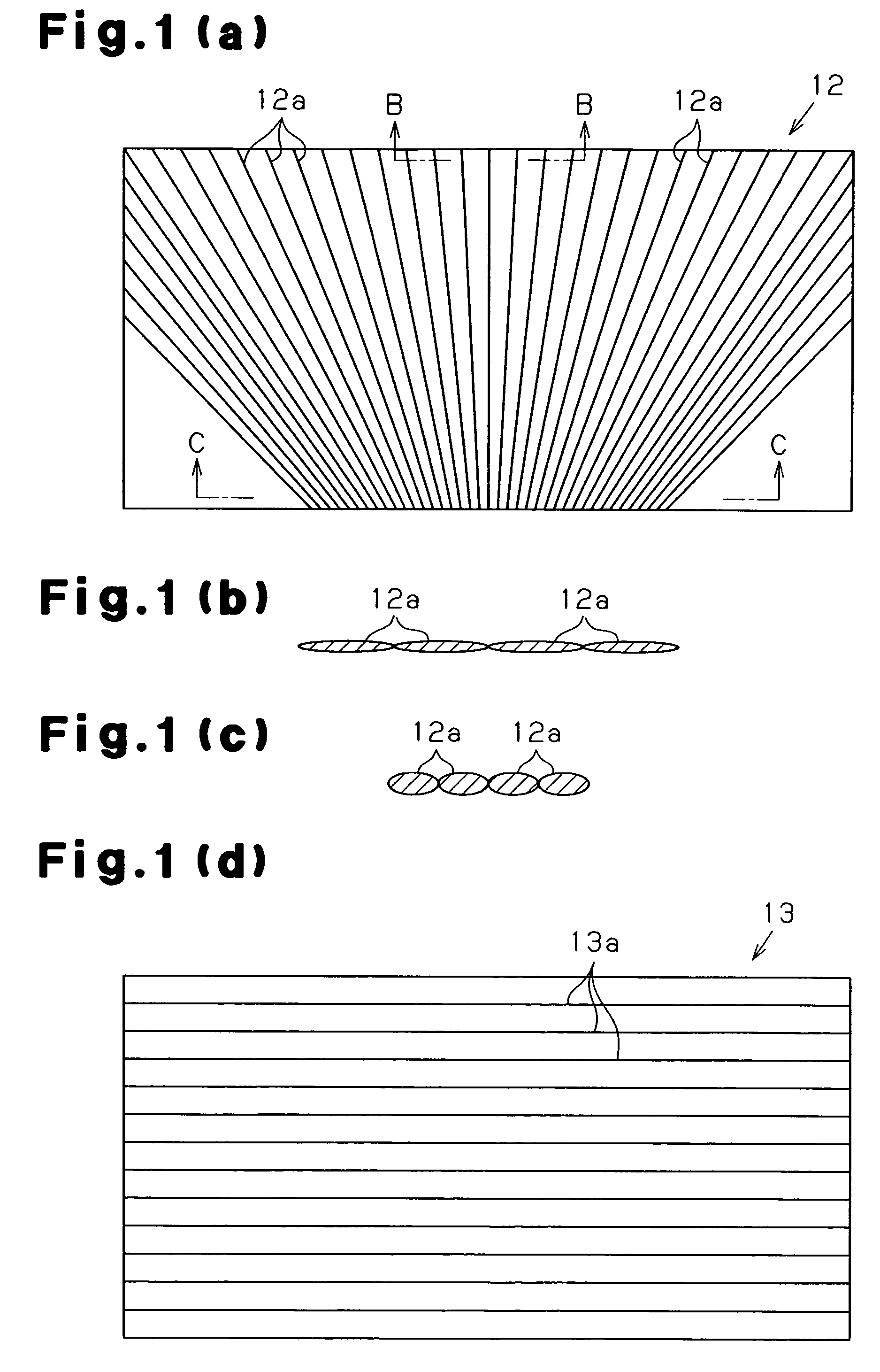
[0112]the present invention will now be described. As shown in FIG. 8(a), an energy absorber 111 is made of a fiber-reinforced resin having a fiber structure 112 as a reinforcing member. As shown in FIG. 8(b), the fiber structure 112 is formed as a plate and includes a stack of fiber layers 113 and binding threads 114. The stack of fiber layers 113 is arranged such that fiber bundles made of filament fibers have at least two axes, or a biaxial structure (in this embodiment, four axes, or a quadraxial structure). The binding threads 114 extend through the stack of fiber layers 113 along the thickness.

[0113]As shown in FIG. 8(a), the stack of fiber layers 113 includes an x thread layers 115 each formed of x threads 115a, a y thread layers 116 each formed of y threads 116a, and a bias thread layers 117, 118 each formed of bias threads 117a, 118a. The x threads 115a are arranged to extend along a direction in which compressive load is applied when the energy absorber 111 is used. The y ...

fourth embodiment

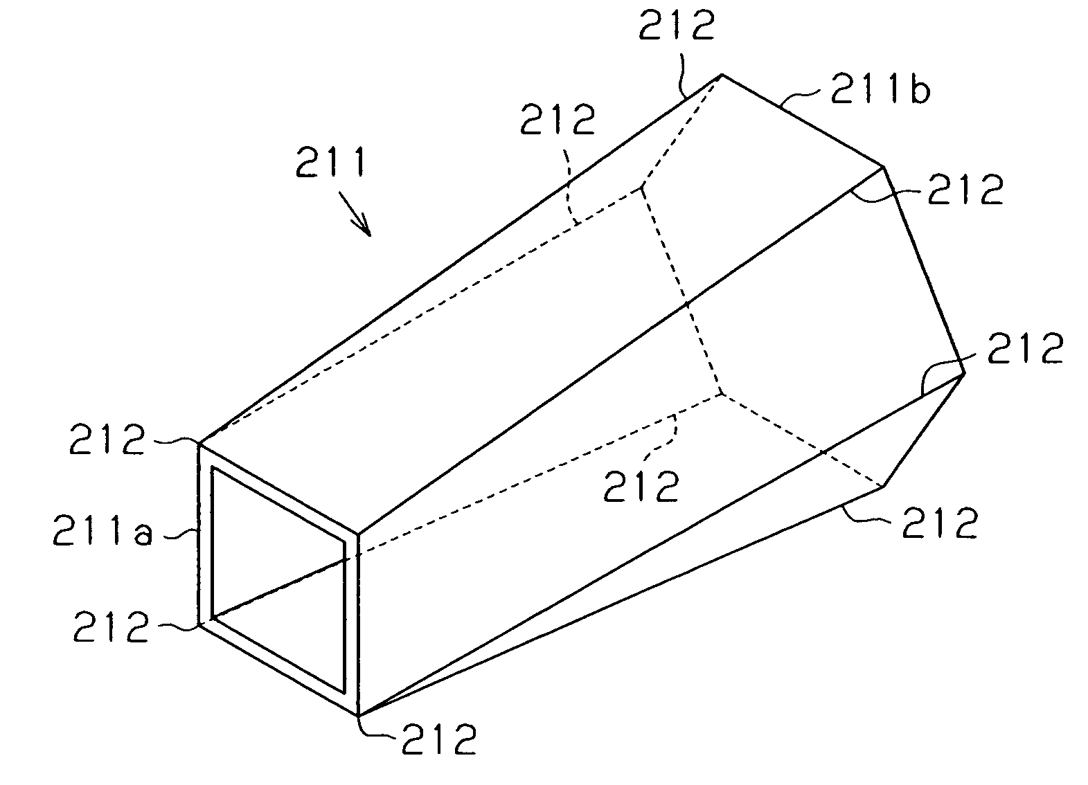
[0151]the present invention will now be described. An energy absorber is made of fiber-reinforced resin. As shown in FIG. 18, a cross-section of the energy absorber 211 perpendicular to a compression direction when in use (direction indicated by arrow in FIG. 18) is varied along the compression direction. The magnitude of load needed for crushing changes depending on the position along the compression direction, accordingly.

[0152]The energy absorber 211 of this embodiment is formed such that the cross-sectional shape is continuously changed along the compression direction. The energy absorber 211 is in a state where a plate member is bent to have corners 212. The number of corners 212 at the proximal end 211b (right end as viewed in FIG. 18) is more than the number of corners 212 at the distal end 211a (left end as viewed in FIG. 18). The number of the corners 212 of the energy absorber 211 is four at the distal end 211a and eight at the proximal end 211b. That is, “the cross-sectio...


PUM

PropertyMeasurementUnit
anglesaaaaaaaaaa
anglesaaaaaaaaaa
thicknessaaaaaaaaaa

Abstract

An energy absorber is crushed upon receiving compressive load, thereby absorbing energy. The energy absorber has a first end and a second end with respect to a direction of the compressive load. The energy absorber is formed of fiber-reinforced resin. The fiber-reinforced resin includes a stack of fiber layers having a compression direction fiber layer. The compression direction fiber layer includes fiber bundles of filament fibers. The fiber bundles are arranged such that the extending direction of the fiber bundles has a component of the direction of the compressive load. The density of the fiber bundles is gradually increased from the first end to the second end. Therefore, compressive load required for crushing is prevented from increasing at an early stage of crushing.

Description

BACKGROUND OF THE INVENTION[0001]The present invention relates an energy absorber and a method for manufacturing the same. More particularly, the present invention pertains to a fiber-reinforced resin energy absorber that is located in a position to which impact is applied and to a method for manufacturing the energy absorber.[0002]Energy absorbers are often provided in portions of a vehicle body that receive impacts, such as a front portion and a rear portion. An energy absorber is deformed when receiving impact, and is crushed to absorb energy. For example, a front side member and a rear side member of a vehicle each play a key role as an impact energy absorbing member (energy absorber). Using metal for energy absorbers increases the weight. Thus, to reduce the weight, energy absorbers are formed of fiber-reinforced resin.[0003]Characteristics desired for such energy absorbers include the ability to be gradually crushed to stably absorb energy without significantly increasing the ...

Claims


Application Information

Patent Timeline
Patent Type & Authority Patents(United States)
IPC IPC(8): D04H1/00B60R21/16B32B3/04B60R19/18F16F7/12
CPCF16F7/124Y10T428/1362Y10T428/24322Y10T428/249924
Inventor HARADA, RYOTSUZUKI, MAKOTOKAMIYA, RYUTANISHIMOTO, AYATSUJI, RYOHEI
Owner TOYOTA IND CORP
Learn More