Laser constructed with multiple output couplers to generate multiple output beams

a laser and output coupler technology, applied in the field of lasers, can solve the problems of inability to fully sever the link, inability to achieve the effect of continuous operation, and inability to damage the passivation structure or the silicon substrate, so as to eliminate the thermal drift of the laser output and minimize the thermal loading variation in the aoms

Inactive Publication Date: 2010-08-05
ELECTRO SCI IND INC
View PDF6 Cites 21 Cited by
  • Summary
  • Abstract
  • Description
  • Claims
  • Application Information

AI Technical Summary

Benefits of technology

[0019]The following are several of the advantages of the invention. Embodiments of this invention perform such pulse picking with minimal thermal loading variation on the AOM to minimize distortion of the laser beam and positioning accuracy. They include an apparatus and a method for generating system on demand laser pulses having stable pulse energies and stable pulse widths at selected wavelengths from the UV to near IR and at high PRFs for high-accuracy laser processing applications, such as memory link severing. The embodiments of this invention provide an efficient, high-throughput apparatus and method for utilizing the working laser pulses.
[0021]An advantage of the present laser beam switching system is that the first and second workpieces receive almost the full power of the laser beam for processing. The total time utilization of the laser beam is increased by almost a factor of two, depending on the processing-to-moving time ratio. This greatly increases system throughput without significantly increasing system cost.
[0023]Employing the beam switching device is advantageous because constant operation of the laser eliminates thermal drifting of the laser output. Moreover, by operating the first and second AOMs with pulse picking methods of this invention, thermal loading variations in the AOMs will be minimized, thereby increasing laser beam positioning accuracy.
[0024]Another advantage of employing the first and second AOMs as a beam switching device is that they can operate as a laser power control device, eliminating a need for a separate laser power controller in a typical laser-based workpiece processing system. Power control is possible because the response times of the AOMs are sufficiently fast for programming laser pulse amplitudes of the switched laser beam during processing of individual target locations on the workpieces. A typical laser processing application is blind via formation in etched-circuit boards, in which it is often necessary to reduce the laser pulse energy when the laser beam reaches the bottom of the via being formed.

Problems solved by technology

For link processing on memory or other IC chips, inadequate laser energy will result in incomplete link severing, while excessive laser energy will cause unacceptable damage to the passivation structure or the silicon substrate.
Unfortunately, due to the nature of the harmonic generation, the pulse-to-pulse energy levels of such UV lasers are particularly sensitive to time variations in PRF and laser pulse interval.
Typical EOM material such as KD*P or KDP suffers from relatively strong absorption at the UV wavelengths, which results in a lower damage threshold of the material at the wavelength used and local heating along the laser beam path within the device, causing changes of the half wave-plate voltage of the device.
Another disadvantage of the EOM is its questionable ability to perform well at a repetition rate over 50 KHz.
One disadvantage of the AOM is its limited diffraction efficiency of about 75-90 percent.
The consequences of thermal loading distort a laser beam passing through AOM 10, resulting in deteriorated laser beam quality and instability in the laser beam path or poor beam positioning accuracy.
However, when the system laser pulses are demanded randomly, such as in laser link processing, these distortions will have the same random nature and cannot be practically corrected.
Laser beam quality distortion resulting from the random thermal loading on the AOM 10 will also deteriorate the focusability of the laser beam, resulting in a larger laser beam spot size at the focusing point.
For applications such as the memory link processing that require the laser beam spot size to be as small as possible, this distortion is very undesirable.

Method used


Image

  • Laser constructed with multiple output couplers to generate multiple output beams
  • Laser constructed with multiple output couplers to generate multiple output beams
  • Laser constructed with multiple output couplers to generate multiple output beams

Examples


Embodiment Construction

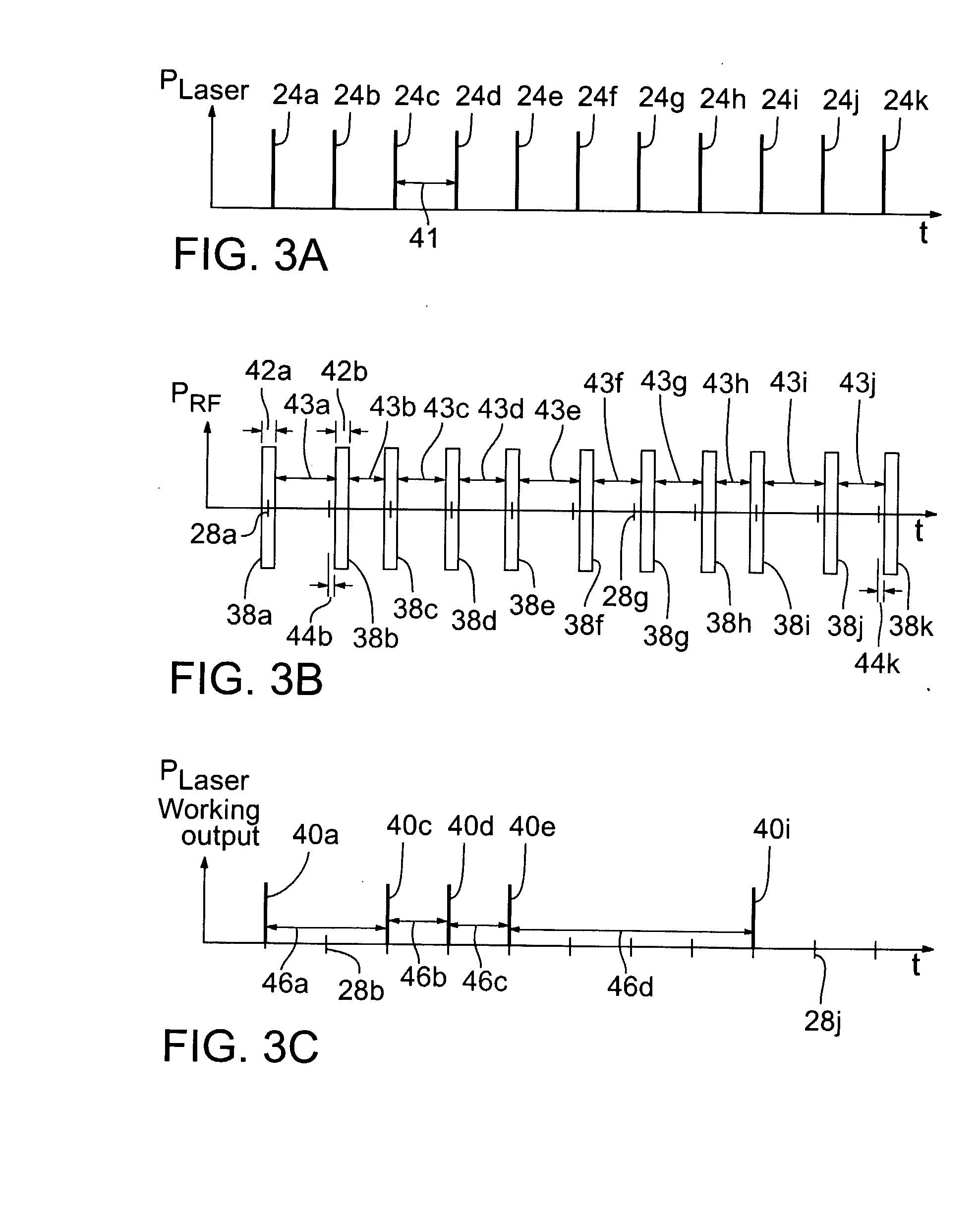
[0042]Thermal loading variations in AOMs, such as prior art AOM 10, can be mitigated by employing pulse picking and laser power control methods shown with reference to FIGS. 3A-3C and 4A-4C, respectively. FIGS. 3A-3C (collectively, FIG. 3) show corresponding timing graphs of laser outputs 24a-24k (collectively, laser outputs 24), RF pulses 38a-38k (collectively, RF pulses 38) applied to prior art AOM 10, and working laser outputs 40a, 40c, 40d, 40e, and 40i (collectively, working laser outputs 40). In particular, FIG. 3A shows laser outputs 24a-24k that are emitted by a laser (not shown) at a constant repetition rate and separated by substantially identical laser output intervals 41. In typical embodiments, the laser output repetition rate may range from about 1 KHz up to about 500 KHz. Exemplary laser output repetition rates range from about 25 KHz to greater than about 100 KHz. For link processing embodiments, each of working laser outputs 40 preferably includes a single laser pul...


PUM

PropertyMeasurementUnit
wavelengthsaaaaaaaaaa
energy wavelengthsaaaaaaaaaa
timeaaaaaaaaaa

Abstract

A laser beam switching system employs a laser coupled to a beam switching device that causes a laser beam to switch between first and second beam positioning heads such that while the first beam positioning head is directing the laser beam to process a workpiece target location, the second beam positioning head is moving to another target location and vice versa. A preferred beam switching device includes first and second AOMs. When RF is applied to the first AOM, the laser beam is diffracted toward the first beam positioning head, and when RF is applied to the second AOM, the laser beam is diffracted toward the second beam positioning head. A workpiece processing system employs a common modular imaged optics assembly and an optional variable beam expander for optically processing multiple laser beams.

Description

RELATED APPLICATIONS[0001]This is a continuation-in-part of U.S. patent application Ser. No. 11 / 000,330, filed Nov. 29, 2004, and a continuation-in-part of U.S. patent application Ser. No. 11 / 000,333, filed Nov. 29, 2004, which is a continuation-in-part of U.S. patent application Ser. No. 10 / 611,798, filed Jun. 30, 2003.TECHNICAL FIELD[0002]This invention relates to lasers and, more particularly, to a method and an apparatus for increasing workpiece machining throughput by alternately switching a single laser beam among two or more beam paths such that one of the beam paths is employed for machining one workpiece while another the beam path is positioned for machining another workpiece.BACKGROUND OF THE INVENTION[0003]Lasers are widely employed in a variety of research, development, and industrial operations including inspecting, processing, and micromachining a variety of electronic materials and substrates. For example, to repair a dynamic random access memory (“DRAM”), laser puls...

Claims


Application Information

Patent Timeline
Patent Type & Authority Applications(United States)
IPC IPC(8): B23K26/00
CPCH01S3/0071B23K26/0673
Inventor OSAKO, YASU
Owner ELECTRO SCI IND INC
Why Eureka
Try Eureka