Notebook-sized computer and input system of notebook-sized computer

a notebook-sized computer and input system technology, applied in the field of notebook-sized computers, can solve the problems of space security, inability to easily move the notebook-sized computer, and the inability to place the pointing device, and achieve the effects of high precision, convenient positioning input, and convenient portability

Inactive Publication Date: 2010-11-30
WACOM CO LTD
View PDF4 Cites 95 Cited by
  • Summary
  • Abstract
  • Description
  • Claims
  • Application Information

AI Technical Summary

Benefits of technology

[0005]The disclosed invention was devised in light of the above-described circumstances, and has as an object the ability to use a position input device with excellent operability in a notebook-sized computer, without detracting from portability or ease of placement.
[0018]According to this invention, in a notebook-sized computer comprising a main unit having a key input portion, position input operation using a position indicator is possible in an operation area positioned in front of the key input portion. By this means, position input using the position indicator can be performed while performing key input operations in the key input portion. There is no need for external connection of any device to the notebook-sized computer, so that the portability and ease of placement of the notebook-sized computer are not compromised. Further, the position detection device provided in the notebook-sized computer utilizes electromagnetic coupling to detect the position of the position indicator, and so position input is possible with high precision, and a light touch in operation can be realized.

Problems solved by technology

For these reasons, users desiring devices with improved operability have connected notebook-sized computers to a mouse or other external device for use; in such cases, however, the notebook-sized computer cannot easily be moved, and there is the further drawback that space must be secured in which to place the pointing device.

Method used


Image

  • Notebook-sized computer and input system of notebook-sized computer
  • Notebook-sized computer and input system of notebook-sized computer
  • Notebook-sized computer and input system of notebook-sized computer

Examples


first embodiment

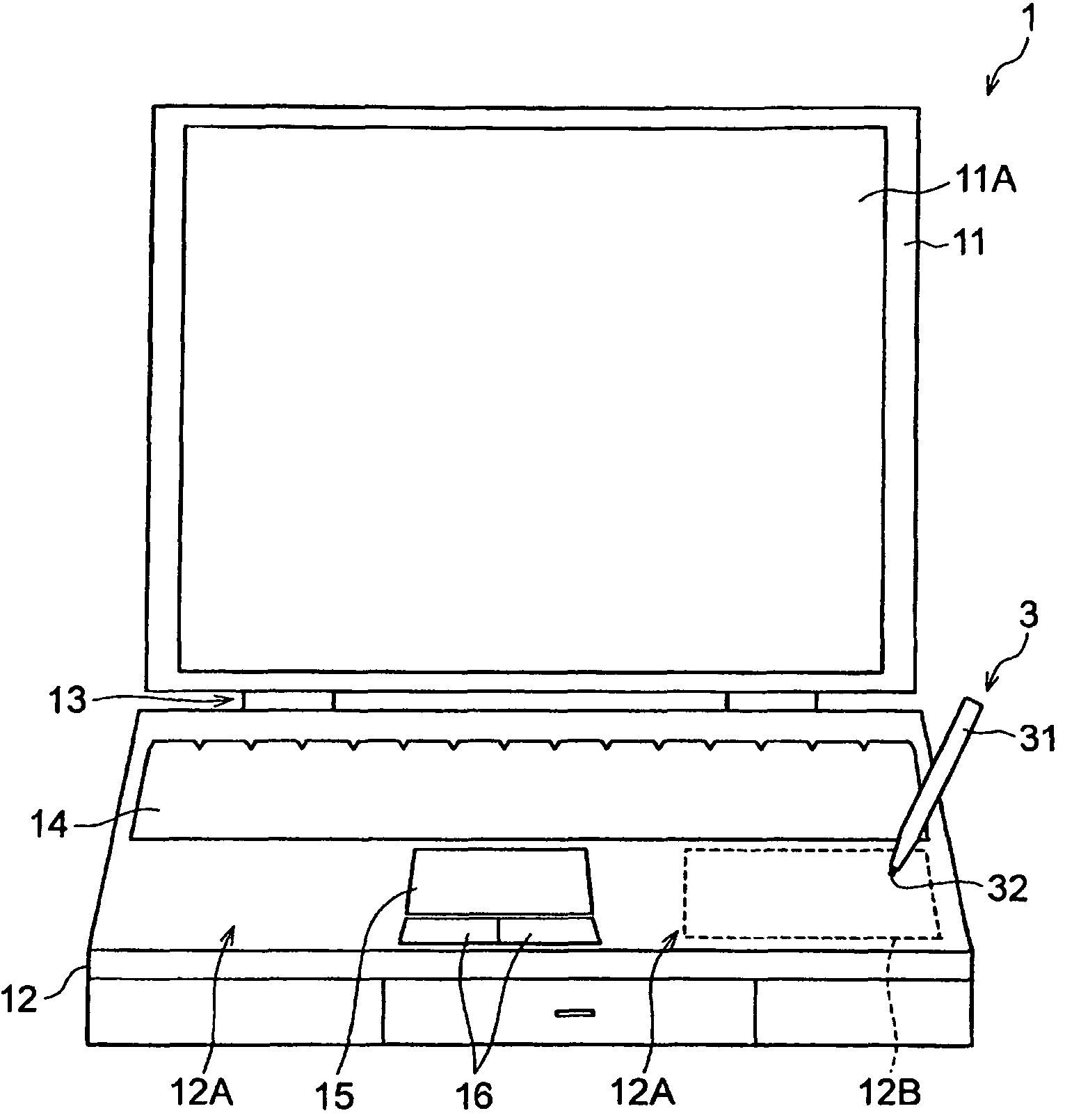
[0026]FIG. 1 is an external view showing a configuration of the notebook-sized computer to which this invention is applied. As shown in FIG. 1, the housing 10 of the notebook-sized computer 1 is configured with a display screen portion 11 and a lower main unit 12 as a main unit. The display screen portion 11 and lower main unit 12 are connected by a hinge portion 13 in a manner enabling folding the display 11 toward and away from the lower main unit 12.

[0027]A liquid crystal display 11A is positioned in the display screen portion 11. Various images are displayed on the liquid crystal display screen 11A, under the control of a CPU (Central Processing Unit), not shown, mounted on the computer main board 18 (FIG. 3), described below.

[0028]In the lower main unit 12 are positioned, as input devices for the user to perform input operations, a keyboard 14 as a key input portion, an input pad 15, and an input switch 16.

[0029]The keyboard 14 is embedded in the upper surface of the lower mai...

second embodiment

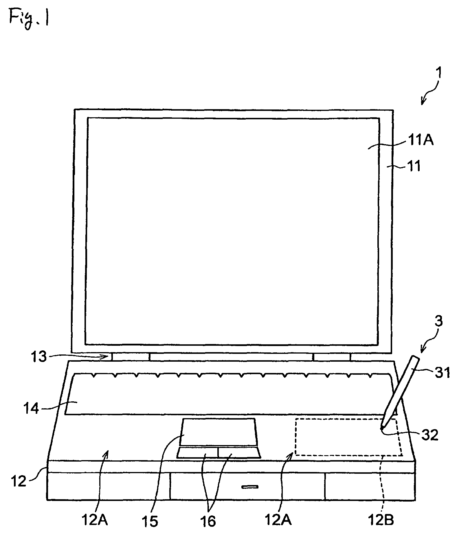
[0082]FIG. 4 shows the principal portions of the lower main unit 12 of the notebook-sized computer 1 of a second embodiment, in which FIG. 4A is an exploded oblique view and FIG. 4B is a cross-sectional view.

[0083]In this second embodiment, the various portions other than the surface sheet 27 described below are configured similarly to those of the notebook-sized computer 1 in the above-described first embodiment, and so the same symbols are used for these portions, and explanations are omitted.

[0084]As shown in FIG. 4(a), in the notebook-sized computer 1 of the second aspect, a surface sheet 27 is affixed at a position equivalent to the effective area 12B of the housing panel 10A.

[0085]The surface sheet 27 functions as an operation area display member, and is a sheet on which is drawn a substantially rectangular frame pattern or a substantially rectangular filled-in pattern, or similar, corresponding to the effective area 12B, which enables the user to visually confirm the position...

third embodiment

[0092]The upper surface of the lower main unit 12 of the notebook-sized computer 1 of the third embodiment is constituted by the housing panel 10B. As shown in FIG. 5, a hole 10C is provided in the palm rest portion 12A of the housing panel 10B. The sensor substrate 25, positioned below the housing panel 10B, is exposed through this hole 10C.

[0093]That is, a depression is formed in the upper surface of the lower main unit 12, and the sensor substrate 25 forms the floor of this depression.

[0094]Here, the size and shape of the hole 10C are arbitrary, but it is preferable that the size and shape substantially match the area of the sensor substrate 25 in which are placed loop coils, that is, the effective area.

[0095]The surface of the sensor substrate 25 exposed through the hole 10C is covered by a cover 28. The cover 28 has the function of protecting the surface of the sensor substrate 25, and further has the function of producing a sense of operation using the input pen 3. During use ...


PUM


Abstract

A notebook-sized computer, comprising a main unit having a display screen portion with a display screen and a key input portion, said notebook-sized computer further comprising an electrostatic capacitance type input pad by which the touch operation by user's finger is detectable, a palm rest portion arranged near the electrostatic capacitive type input pad underneath which the sensor substrate of a position detection device is placed, and a position detection device comprising the sensor substrate mounted internally in said notebook-sized computer and including a plurality of loop coil groups realized by one or a plurality of patterns on the sensor substrate, each of the loop coils comprising at least one turn, a position detection circuit electrically connected to the loop coils within the sensor substrate, a position indicator having a resonance circuit coupled to said coils in electromagnetic coupling fashion, wherein the detection circuit detects operations initiated by using the position indicator when the position indicator is placed in contact with or suspended a prescribed distance above the sensor substrate.

Description

CROSS-REFERENCE TO RELATED APPLICATIONS AND CLAIM TO PRIORITY[0001]The present invention contains subject matter related to Japanese Patent Application JP 2005-142579, filed in the Japanese Patent Office on May 16, 2005, the entire contents of which are incorporated herein by reference and to which priority is claimed.FIELD OF THE INVENTION[0002]This invention relates to a notebook-sized computer having a display screen, and to an input system for a notebook-sized computer.BACKGROUND OF THE INVENTION[0003]Normally, notebook-sized computers have, in addition to a keyboard as a key input device, a touchpad or other position input device, also called a pointing device such as shown in Japanese Patent Laid-open No. 2000-200146 (FIG. 31)SUMMARY OF THE INVENTION[0004]The position input devices in notebook-sized computers of the prior art are required to be lightweight and compact, and there remains room for improvement in operability. For these reasons, users desiring devices with improve...

Claims


Application Information

Patent Timeline
Patent Type & Authority Patents(United States)
IPC IPC(8): G09G5/00G06F3/041
CPCG06F1/1616G06F1/169G06F3/0414G06F2203/0331
Inventor ONODA, NAOTO
Owner WACOM CO LTD
Why Eureka
Try Eureka