Imaging device, and control method for imaging device

a control method and imaging device technology, applied in the direction of printers, instruments, camera focusing arrangement, etc., can solve the problem of no longer being able to use an af (auto focus) mechanism, and achieve the effect of small time lag and high precision

Inactive Publication Date: 2010-11-30
OLYMPUS CORP
View PDF4 Cites 9 Cited by
  • Summary
  • Abstract
  • Description
  • Claims
  • Application Information

AI Technical Summary

Benefits of technology

[0008]The present invention has as its object to provide an imaging device that can perform focusing with a small time lag and with high precision in the case of imaging from a live view display function, and a control method for an imaging device.

Problems solved by technology

However, in a digital single lens reflex camera, in order to carry out live view display a movable mirror that is arranged in the imaging optical path is temporarily retracted, which means that during live view it is no longer possible to use an AF (Auto Focus) mechanism that employs a conventional phase difference method where a defocus amount of the photographing leans is detected using subject light flux that has been reflected by a sub-mirror attached to the moveable mirror.

Method used


Image

  • Imaging device, and control method for imaging device
  • Imaging device, and control method for imaging device
  • Imaging device, and control method for imaging device

Examples


first embodiment

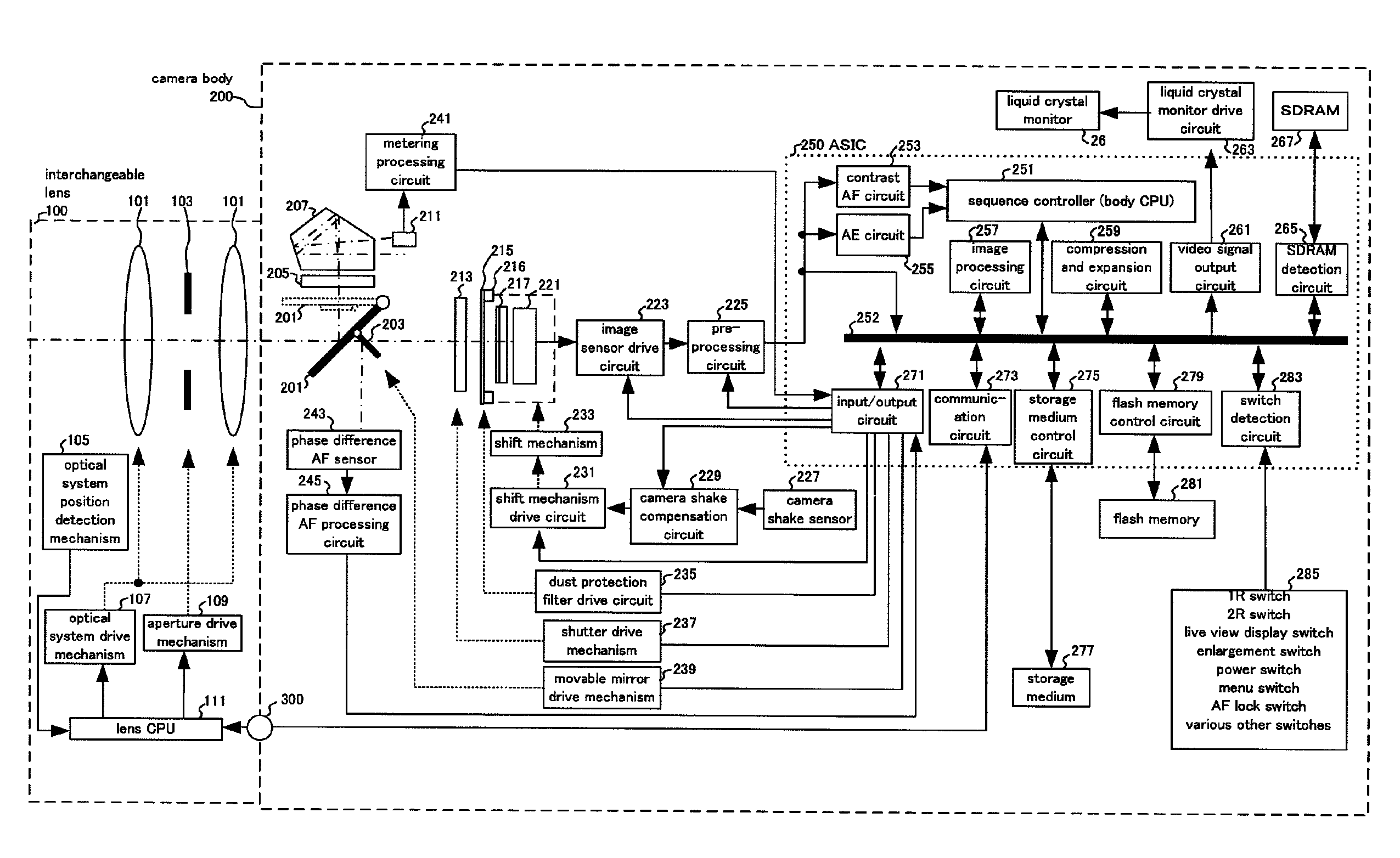
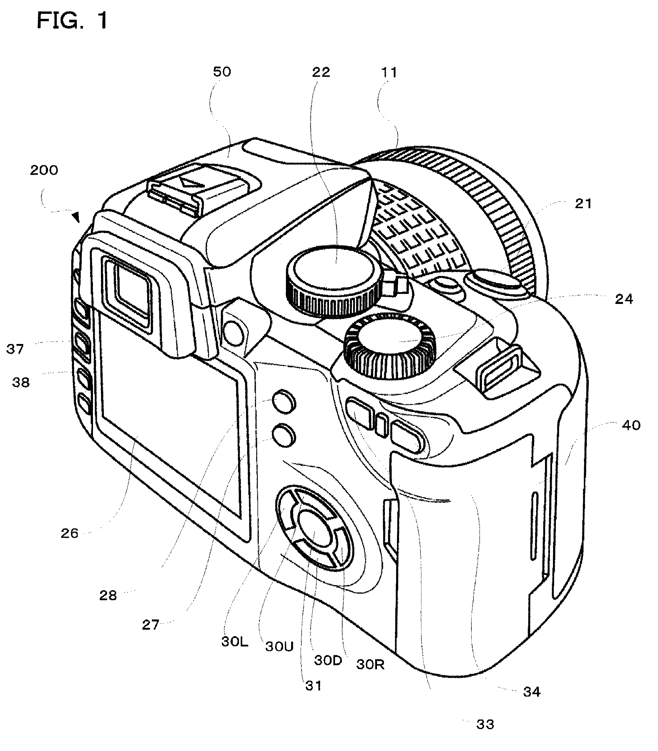
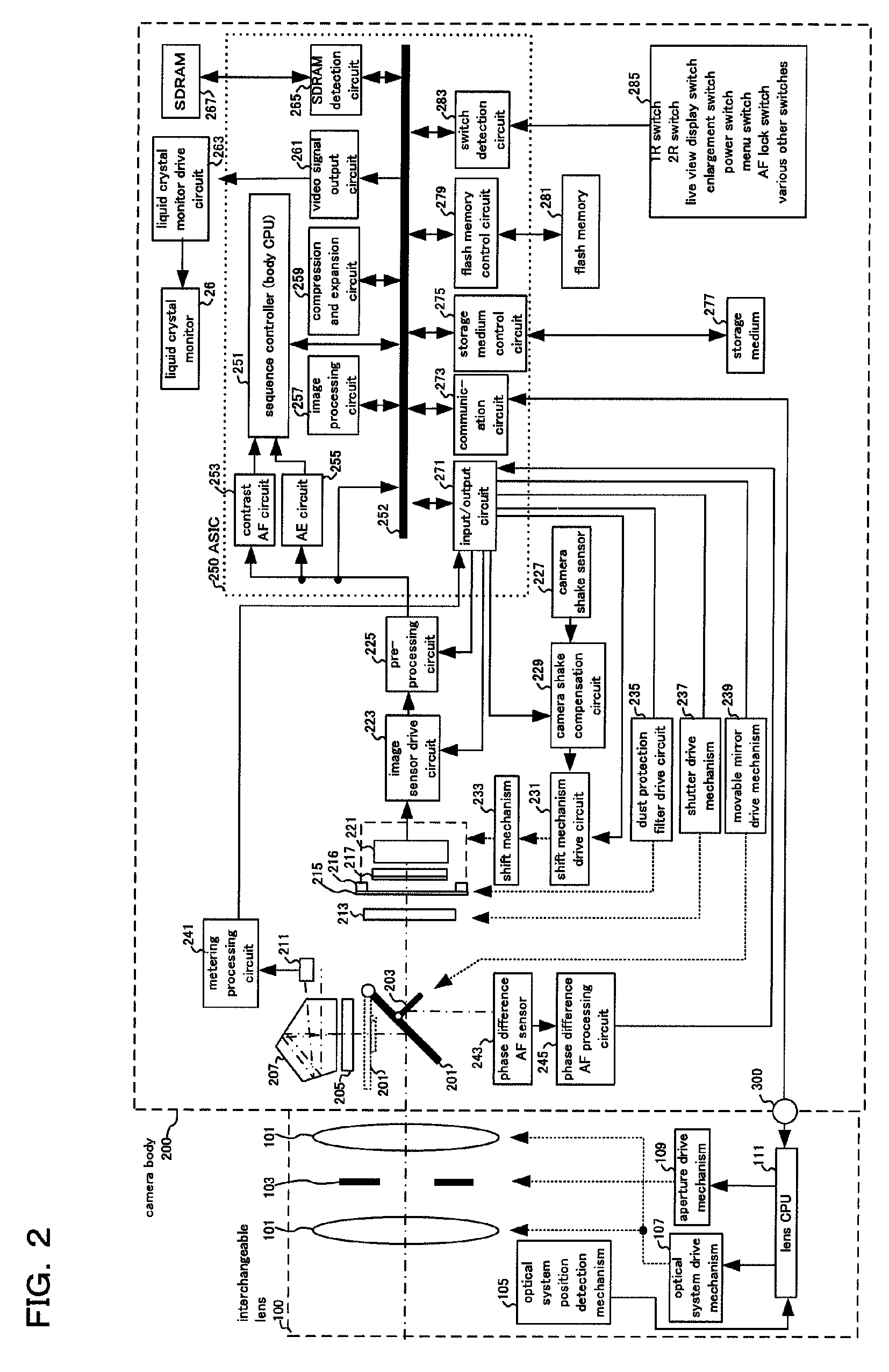
[0041]In the following, one preferred embodiment using a digital single lens reflex camera adopting the present invention will be described using the drawings. FIG. 1 is an external perspective drawing of a digital single lens reflex camera relating to the present invention seen from a rear surface.

[0042]A release button 21, exposure mode dial 22, information setting dial 24, strobe 50 etc. are arranged on the upper surface of the camera body 200. The release button 21 has a first release switch that turns on if the photographer presses the button down halfway, and a second release switch that is turned on when the button is pressed down fully. By turning this first release switch (hereafter called 1R) on (photographing preparation operation), the camera carries out exposure preparation operations such as focal point detection, focusing of the photographing lens, and light measurements for the subject brightness, and by turning the second switch (hereafter called 2R) on (photographi...

second embodiment

[0187]In this way, in the present invention, if the release button is fully operated (#53→Y #107 Y) when enlarged display is being carried out in live view display mode (#55→#75 in FIG. 4), and there is a transition to a shooting operation, defocus amount is detected using a phase difference AF method for detection points contained in the enlarged display region (#182 of FIG. 20). It is therefore possible to carry out automatic focus adjustment for a region where the photographer has performed enlarged display, that is, for a subject the photographer wants to focus on. Also, since phase difference AF is not carried out for all focus detection points, it is possible to reduce the ranging time, and it is possible to ensure higher precision focus adjustment using phase difference AF.

[0188]Further, in the determination of step #113 in this embodiment, if there is the second focus display, that is, focus has been achieved with high precision contrast AF, the phase difference AF of step #...

third embodiment

[0210]In this manner, in the present invention, in the case where image magnification at the time of first focus using first contrast AF control is larger than ¼ the maximum image magnification of the fitted interchangeable lens 100 (Y at step #1245), that is, when the subject is at a short distance, in other words when focus is in a region of shallow depth of field, operation is carried out up to high precision second contrast AF control. Specifically, at the time of first contrast AF control, in the event that the subject is to the short distance side (a shallow depth of field region), the short distance flag is set, and at the time of second contrast AF control a transfer is not made to the shooting operation (if the short distance flag has been set in #1283, determination of the 2R switch in #285 is not carried out) even if the release button 21 has been pressed down fully and the 2R switch is on, until a high precision focus state has been reached (#277). If the result of deter...


PUM


Abstract

An imaging device comprising a first contrast AF unit that obtains contrast information of a subject image from subject image data, and guides a photographing lens to within a first in-focus permissible based on the contrast information; a phase difference AF unit for receiving subject light flux to detect a defocus amount of the photographing lens by the phase difference method, and guiding the photographing lens to within a second in-focus permissible range in response to the detection results; a release button having a two stage operating arrangement of half pressed and fully pressed; and a control unit for, when the release button has been pressed down halfway during execution of the live view display operation, executing a focusing operation using the first contrast AF unit, and, after that, when the release button is pressed down fully, executing a focusing operation using the phase contrast AF unit.

Description

[0001]Benefit is claimed, under 35 U.S.C. §119, to the filing date of prior Japanese Patent Application Nos. 2007-201125 filed on Aug. 1, 2007, 2007-201127 filed on Aug. 1, 2007, 2007-202554 filed on Aug. 3, 2007, 2007-216540 filed on Aug. 22, 2007, and 2007-216547 filed on Aug. 22, 2007. These applications are expressly incorporated herein by reference. The scope of the present invention is not limited to any requirements of the specific embodiments described in the applications.BACKGROUND OF THE INVENTION[0002]1. Field of the Invention[0003]The present invention relates to a digital camera having a live view display function, and in detail relates to an imaging device, having a so-called live view display function (also called an electronic viewfinder function) for displaying an image acquired by an image sensor on a display unit, capable of focusing a photographing lens using an image signal during this live view display, and to a control method for an imaging device.[0004]2. Des...

Claims


Application Information

Patent Timeline
Patent Type & Authority Patents(United States)
IPC IPC(8): G03B13/00H04N5/232
CPCG02B7/38G03B13/36H04N23/663H04N23/67H04N23/667H04N23/63
Inventor KUNISHIGE, KEIJIMIYAZAKI, SATOSHI
Owner OLYMPUS CORP
Why Eureka
Try Eureka