Spray gun reservoir with oversize, fast-fill opening

a spray gun and reservoir technology, applied in the direction of rigid containers, volume measurement, functional valve types, etc., can solve the problems of time-consuming cleaning of spray guns and pots, spillage of liquid, health hazards for operators, etc., and achieve the effect of improving further

Inactive Publication Date: 2010-12-07
3M INNOVATIVE PROPERTIES CO
View PDF131 Cites 15 Cited by
  • Summary
  • Abstract
  • Description
  • Claims
  • Application Information

AI Technical Summary

Benefits of technology

[0010]The present invention is intended to improve further our existing system and provide additional benefits and advantages for the user.
[0011]More specifically, at least one embodiment of the present invention provides a liquid supply assembly for use with a spray gun that allows liquid to be added in a simple manner.

Problems solved by technology

Cleaning the spray gun and pot is time consuming and often requires the use of solvents which are costly and may present a health hazard to the operator.
Dis-assembly and re-assembly of the reservoir is time consuming and can result in spillage of liquid especially when the lid is removed from the liner.
Also, removing the lid to add more liquid to the liner increases the risk of contamination from other sources, e.g. dust or dirt.
The alternative of adding liquid to the reservoir through the spout in the lid so as to avoid dis-assembly is slow due to the spout being of small size compatible with the connection to the spray gun so that liquid cannot be freely poured into the reservoir through the spout.
Access to the filter requires dis-assembly of the reservoir and the presence of such filter further slows the addition of liquid to the reservoir through the spout.
Furthermore, if the liquid contains solid particles these will be trapped on the wrong side of the filter.
This may lead to a blockage within the spray gun.

Method used


Image

  • Spray gun reservoir with oversize, fast-fill opening
  • Spray gun reservoir with oversize, fast-fill opening
  • Spray gun reservoir with oversize, fast-fill opening

Examples


first embodiment

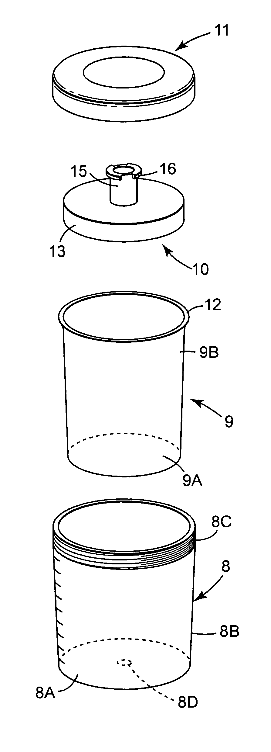
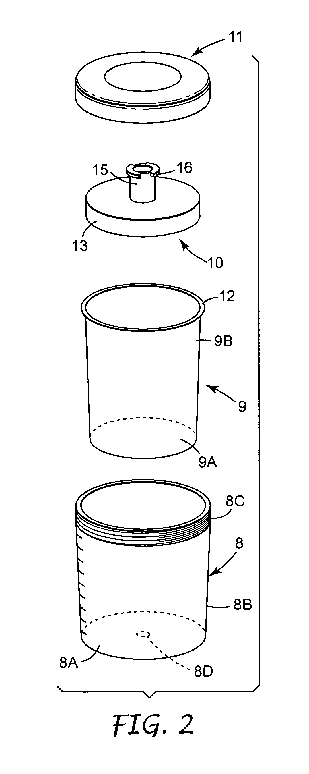
[0081]Referring now to FIGS. 8 to 12 of the drawings, there is shown the present invention which enables the user to add paint to the reservoir without disassembly of the reservoir. For convenience, like reference numerals in the series 100 are used throughout to indicate parts corresponding to FIGS. 1 to 7 and the construction and operation of similar parts will be understood from the description above and will not be further described in detail.

[0082]As shown the paint pot 106 includes an outer container 108, a disposable liner 109, a disposable lid 110 and a collar 111 that are assembled in similar manner to the previous embodiment. In accordance with the present invention, the lid 110 has a central opening 130 bounded by an external tubular spigot 131 and a separate cap member 132 is provided for connecting the pot 106 to a spray gun (not shown). By locating the opening 130 centrally, the size of the opening 130 can be maximised for a given available space.

[0083]The cap member 1...

second embodiment

[0092]Referring now to FIG. 13, there is shown the present invention in which like reference numerals in the series 200 are used to indicate parts corresponding to the previous embodiments and the construction and operation of similar parts will be readily understood from the description already given and will not be further described in detail.

[0093]In this second embodiment, the liner 209 and lid 210 are permanently joined together. For example, the liner 209 and lid 210 may be formed integrally in one piece by blow moulding. Alternatively, the liner 209 and lid 210 may be formed separately by moulding and connected together by welding, adhesive or other suitable means 211 of forming a permanent join therebetween.

[0094]The reservoir formed by permanently joining the liner 209 and lid 210 may be used without the outer container and collar of the previous embodiments. Alternatively, some form of external support for the liner 209 may be provided to protect the liner 209 and to impro...

third embodiment

[0098]In this third embodiment, the cap member 332 for connecting the reservoir (not shown) to the spray gun (not shown) is provided with releasable connector means separate from the spout 315. The connector means comprises a pair of hook members 339, 340 arranged on opposite sides and spaced from the spout 315. Each hook member 339, 340 is similar and has an enlarged head 341, 342 respectively with a chamfer face 341a, 342a terminating at an undercut rib 341b, 342b.

[0099]The inlet adaptor 318 on the spray gun has an external flange 343 at the outer end for co-operating with the hook members 339, 340 to secure releasably the reservoir to the spray gun with the spout 315 received in the socket 319. In this embodiment; the spout 315 has external annular ribs 344 that provide a fluid-tight seal within the socket 319. It will be understood, however, that any suitable sealing means may be provided such as one or more O-rings in the socket 319 and / or on the spout 315.

[0100]As best shown ...


PUM


Abstract

A spray gun reservoir has an oversize central opening 130 at one end allowing liquid to be added to the reservoir for fast filling with reduced risk of spillage. A cap member 132 is connectable to the reservoir and has a spout 115 providing a fluid outlet of reduced size relative to the opening 130 for connection to the spray gun. The reservoir can be disconnected from the cap member 132 when it is desired to add liquid to the reservoir. In this way, the reservoir can be re-filled in use.

Description

FIELD OF THE INVENTION[0001]This invention concerns improvements in or relating to liquid supply assemblies for use with spraying apparatus such as a spray gun. More especially, the invention relates to liquid supply assemblies in which a reservoir containing the liquid to be sprayed is mounted on the spray gun.BACKGROUND OF THE INVENTION[0002]Spray guns are widely used to apply a liquid to a substrate in a variety of industries. In the known spray guns, the liquid is contained in a reservoir attached to the gun from where it is fed to a spray nozzle. On emerging from the spray nozzle, the liquid is atomised and forms a spray with compressed air supplied to the nozzle. The liquid may be gravity fed or suction fed or, more recently, pressure fed by an air bleed from the compressed air line to the reservoir or even from the spray gun itself.[0003]A common application of spray guns is in vehicle body repair shops when re-spraying a vehicle that has been repaired following an accident. ...

Claims


Application Information

Patent Timeline
Patent Type & Authority Patents(United States)
IPC IPC(8): A62C13/62B65D88/54F16K15/14A01G25/14
CPCB05B7/2408B05B7/2478A62C13/003Y10S239/14Y10T137/7879
Inventor JOSEPH, STEPHEN C. P.SILTBERG, DANIEL E.
Owner 3M INNOVATIVE PROPERTIES CO
Why Eureka
Try Eureka