Bendable portion control mechanism of an endoscope

a control mechanism and endoscope technology, applied in the field of bendable portion control mechanism of endoscope, can solve the problems of troublesome adjustment, time-consuming, and troublesome adjustment of endoscope during routine maintenance after use by the operator, and achieve the effect of short time and easy adjustmen

Inactive Publication Date: 2010-12-07
HOYA CORP
View PDF9 Cites 4 Cited by
  • Summary
  • Abstract
  • Description
  • Claims
  • Application Information

AI Technical Summary

Benefits of technology

[0009]The present invention provides a bendable portion control mechanism of an endoscope provided with two bent state holding mechanisms which are respectively installed in the water-sealed spaces of two control knobs, one of the which being provided on top of the other and coaxially arranged, wherein adjustments to operational characteristics of the bent state holding mechanisms can be made easily with a small number of man-hours in a short amount of time.
[0020]According to the present invention, since the bendable portion control mechanism is configured to allow the control knobs to be detached from and attached to the control portion while preventing the control knobs from interfering with any element of the two bent state holding mechanisms, to thereby make it possible to adjust the operational characteristics of each of the two bent state holding mechanisms simply by detaching the two control knobs, adjustments to operational characteristics of the two bent state holding mechanisms (especially the bent state holding mechanism which is positioned in the water-sealed internal space of one of the two control knobs which is positioned closest the base of the control portion) can be made easily with a small number of man-hours in a short amount time.

Problems solved by technology

Accordingly, it is troublesome to make an adjustment to the degree of frictional resistance which is exerted on the rotating operation of the control knob positioned closer to the base of the control portion; moreover, a need to make an adjustment to the degree of frictional resistance which is exerted on the rotating operation of the other control knob that is positioned farther from the base of the control portion arises after the control knob positioned closer to the base of the control portion is re-mounted to the control portion.
Therefore, fine adjustments made to the endoscope during assembly of the endoscope after the bendable portion control mechanism is assembled and adjustments made to the endoscope during routine maintenance after use by the operator are very troublesome and time-consuming.

Method used


Image

  • Bendable portion control mechanism of an endoscope
  • Bendable portion control mechanism of an endoscope
  • Bendable portion control mechanism of an endoscope

Examples


Embodiment Construction

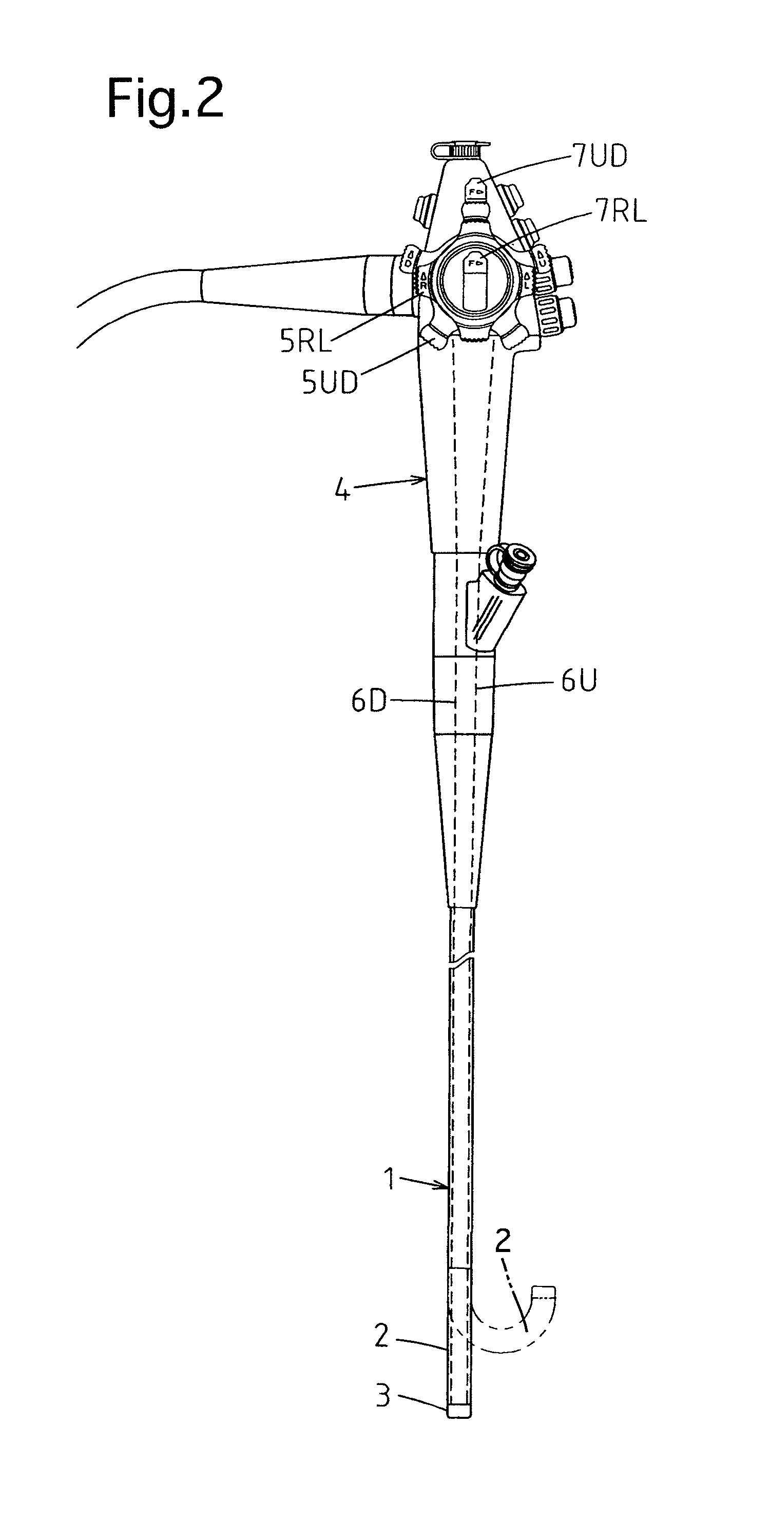
[0031]FIG. 2 shows the general configuration of an embodiment of the electronic endoscope, in which an image captured thereby is displayed on a monitoring screen (not shown). The endoscope is provided with a flexible insertion portion 1 and a control portion 4 coupled to the proximal end of the insertion portion 1. The insertion portion 1 is provided in the vicinity of the distal end (free end) thereof with a remote-controllable bendable portion 2, and is further provided with an end body 3 fixed to the end (free end) of the bendable portion 2. An objective window and others (not shown) are provided in the end body 3.

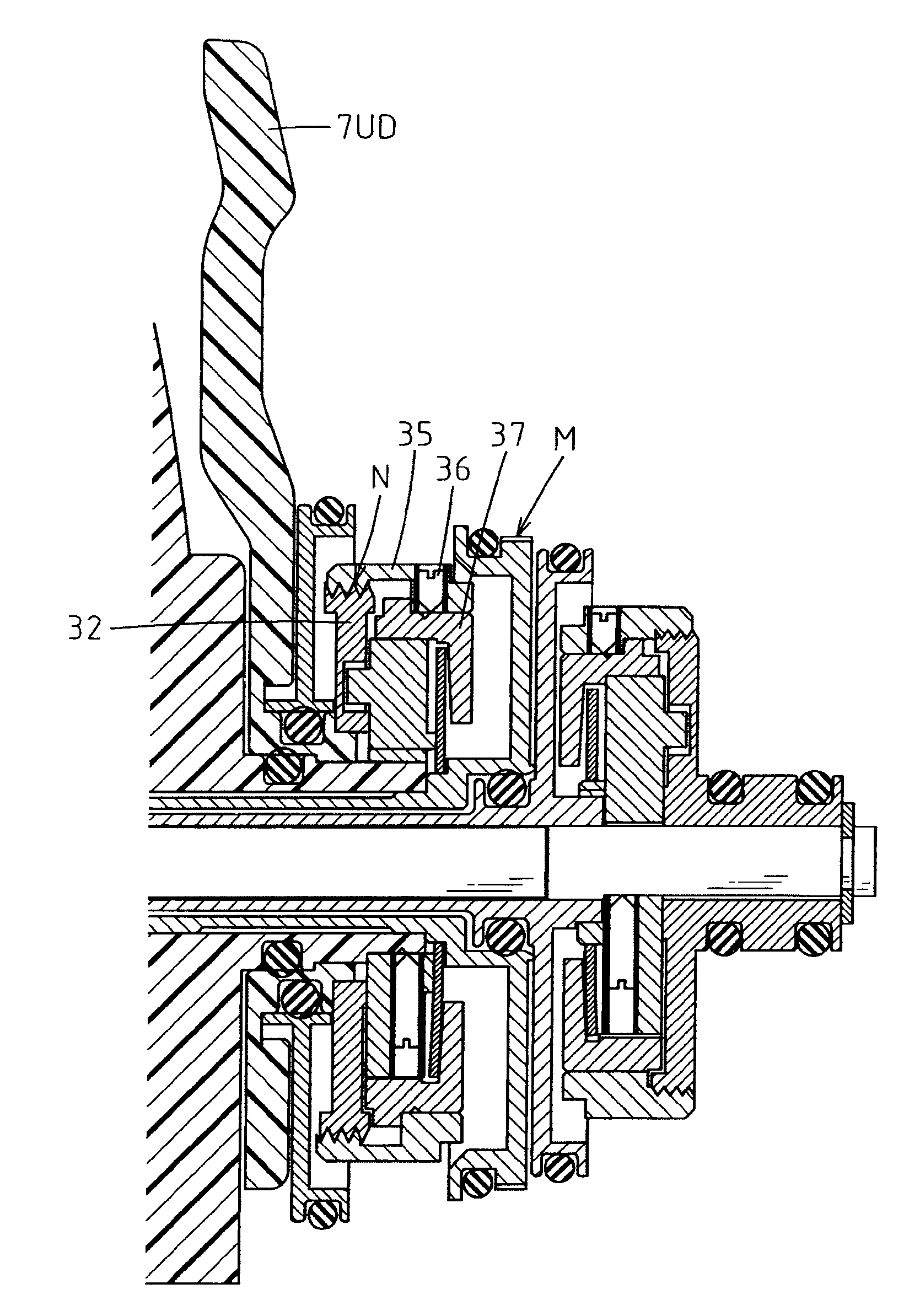
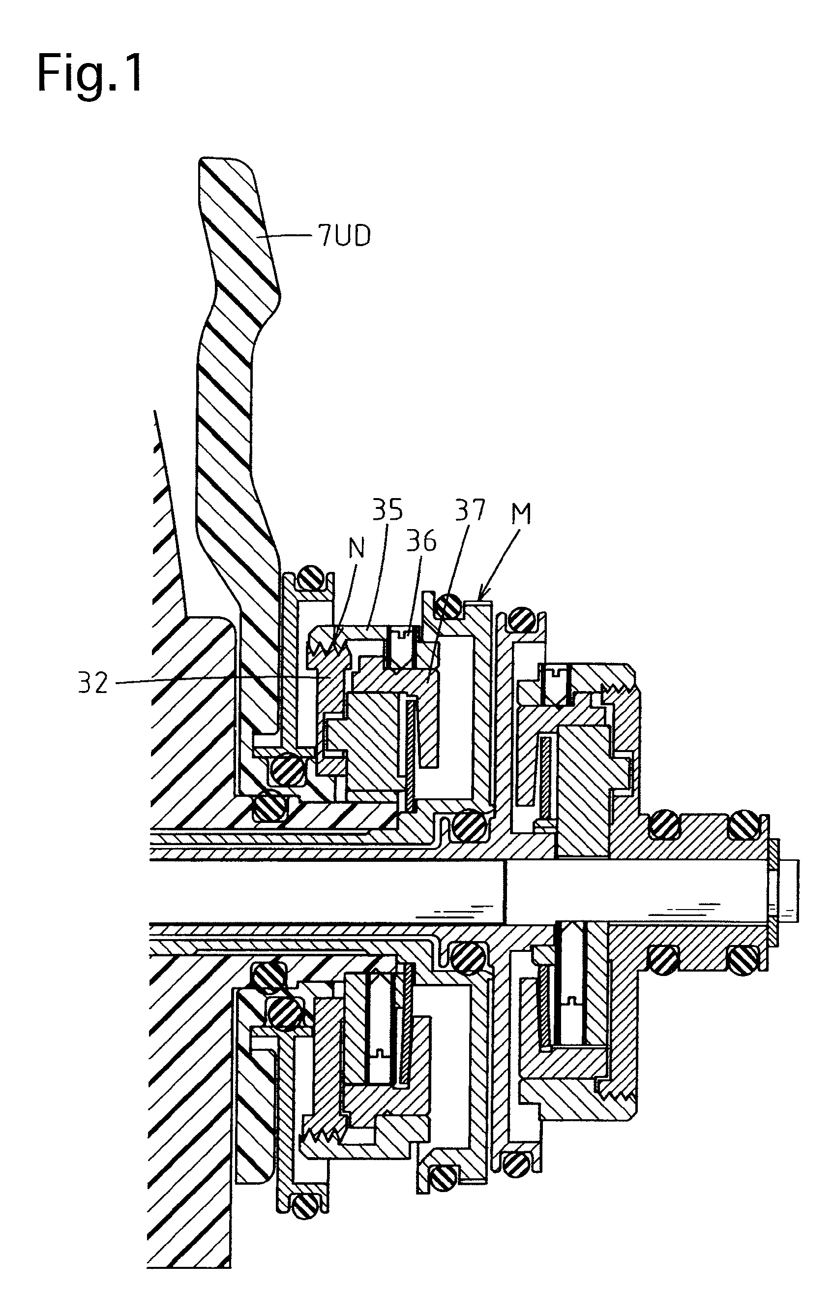
[0032]The control portion 4, which is coupled to the proximal end of the insertion portion 1, is provided thereon with a U-D control knob 5UD for bending the bendable portion 2 upward and downward and an R-L control knob 5RL for bending the bendable portion 2 rightward and leftward. The R-L control knob 5RL is provided on top of the U-D control knob 5UD and are coaxiall...


PUM


Abstract

A bendable portion control mechanism of an endoscope including a control portion and an insertion portion, includes two manually-rotatable control knobs, one of which being provided on top of the other and disposed coaxially with each other, for bending the bendable portion in two orthogonal directions, each of the control knobs including a water-sealed internal space; and two bent state holding mechanisms, provided in the two water-sealed internal spaces, respectively, for holding a bent state of the bendable portion in the two orthogonal directions by exerting frictional resistance on rotating operations of the two control knobs. The two control knobs detach from and attach to the control portion without interfering with the two bent state holding mechanisms so that it is possible to adjust operational characteristics of each of the two bent state holding mechanisms upon detaching the two control knobs, respectively.

Description

BACKGROUND OF THE INVENTION[0001]1. Field of the Invention[0002]The present invention relates to a bendable portion control mechanism of an endoscope.[0003]2. Description of the Related Art[0004]A typical endoscope with a bendable portion capable of being freely bent in four directions (upward, downward, leftward and rightward) is provided with a U-D control knob for bending the bendable portion upward and downward, an R-L control knob for bending the bendable portion rightward and leftward, a U-D bent state holding mechanism for holding a bent state of the bendable portion in the upward / downward direction by exerting frictional resistance on the rotating operation of the U-D control knob, and an R-L bent state holding mechanism for holding a bent state of the bendable portion in the rightward / leftward direction by exerting frictional resistance on the rotating operation of the R-L control knob in the control portion of the endoscope. The U-D control knob and the R-L control knob ar...

Claims


Application Information

Patent Timeline
Patent Type & Authority Patents(United States)
IPC IPC(8): A61B1/00
CPCA61B1/0052G02B23/2476
Inventor MARUYAMA, YOSHINORI
Owner HOYA CORP
Why Eureka
Try Eureka