Clipping and culling artwork using a graphics processing unit

Active Publication Date: 2010-12-07
ADOBE INC
View PDF15 Cites 41 Cited by
  • Summary
  • Abstract
  • Description
  • Claims
  • Application Information

AI Technical Summary

Benefits of technology

[0012]According to a further embodiment, the artwork may be automatically grouped into one or more groups prior to being sent to the GPU. In identifying similarities among objects in the artwork and assigning t

Problems solved by technology

As the power and complexity of personal computer systems increase, graphics operations and graphical data are likewise increasing in complexity.
Rendering a large and

Method used


Image

  • Clipping and culling artwork using a graphics processing unit
  • Clipping and culling artwork using a graphics processing unit
  • Clipping and culling artwork using a graphics processing unit

Examples


Embodiment Construction

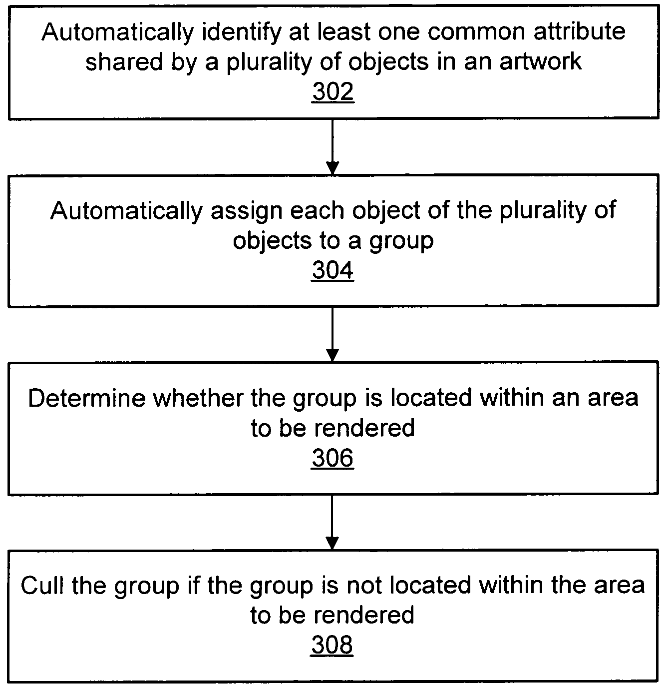
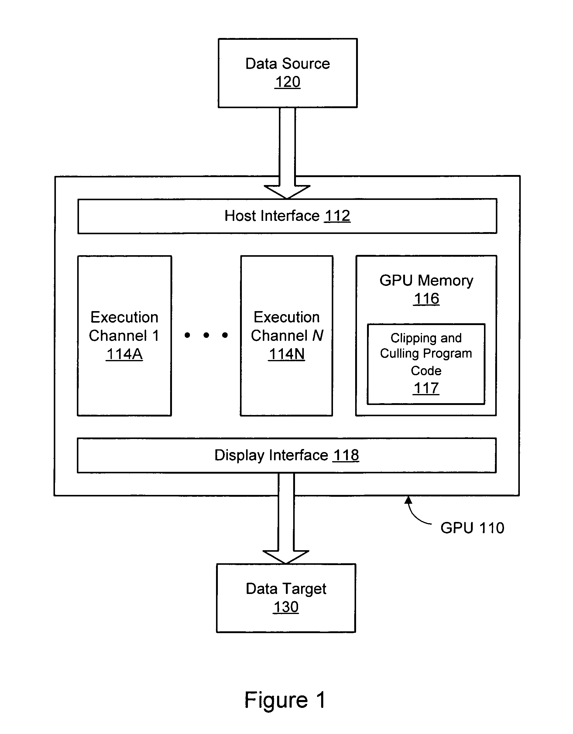
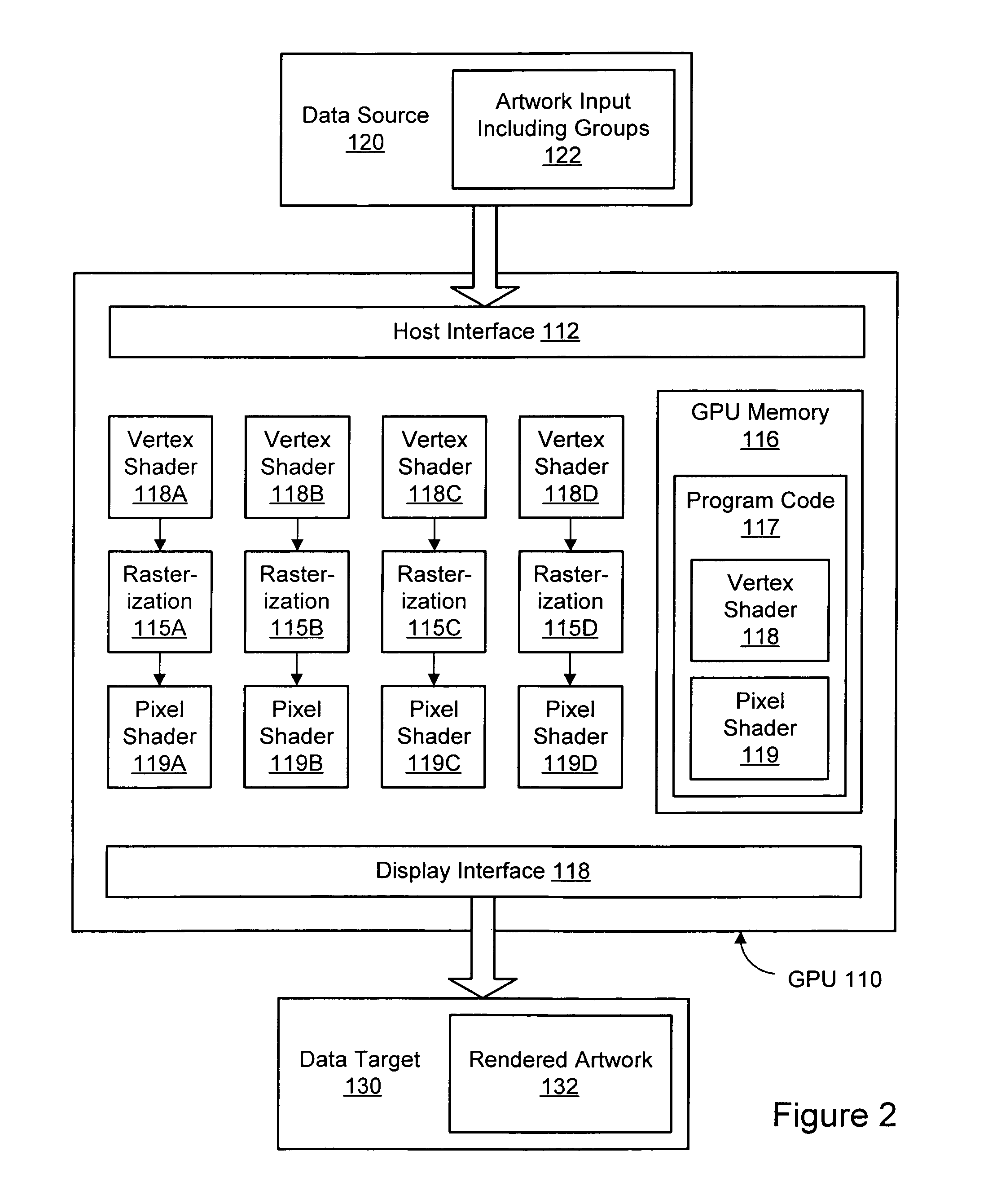
[0022]To reduce computational demands associated with rendering complex artwork on computer systems, the number of necessary clipping and / or culling operations may be reduced by automatically grouping artwork according to a set of rules. A graphics processing unit (GPU) may then be used to perform aspects of the clipping and / or culling operations. FIG. 1 is a block diagram illustrating one embodiment of a system configured for clipping and culling on a GPU according to the techniques described herein. A graphics processing unit (GPU) 110, also referred to herein as a graphics processor, may comprise a dedicated graphics rendering device associated with a computer system. An example of a suitable computer system 900 for use with a GPU 110 is illustrated in FIG. 8. Turning back to FIG. 1, a GPU 110 may include numerous specialized components configured to optimize the speed of rendering graphics output. For example, a GPU 110 may include specialized components for rendering three-dime...


PUM


Abstract

A method, system, and computer-readable storage medium are disclosed for rendering artwork using a graphics processing unit (GPU). The GPU may comprise a depth buffer and a stencil buffer. Artwork input comprising one or more dirty regions and one or more clip paths may be received at the GPU. A culling operation may be performed on the artwork input. The culling operation may comprise configuring the depth buffer to reject pixels located outside a union of the one or more dirty regions. A clipping operation may be performed on the artwork input. The clipping operation may comprise configuring the stencil buffer to reject pixels located outside an intersection of the one or more clip paths.

Description

BACKGROUND[0001]1. Field of the Invention[0002]The present invention is directed to computer systems; and more particularly, it is directed to rendering two-dimensional artwork using computer systems.[0003]2. Description of the Related Art[0004]As the power and complexity of personal computer systems increase, graphics operations and graphical data are likewise increasing in complexity. Graphical data, particularly two-dimensional graphical data, may typically be expressed in a structured format that complies with a particular specification or model for representing such data. Instead of requiring application programs to describe every page as a full-resolution pixel array, a high-level imaging model may enable applications to describe the appearance of pages containing text, graphical shapes, and sampled images in terms of abstract graphical elements rather than directly in terms of device pixels. Such specifications and models may often be implemented across multiple computing pla...

Claims


Application Information

Patent Timeline
IPC IPC(8): G06T15/40G06T1/00G06F15/00
CPCG06T15/405G06T11/40G06T2200/28
Inventor PARENTEAU, ALEXANDRE S.CLARK, DANIEL J.
Owner ADOBE INC
Why Eureka
Try Eureka