Heater unit for installation on valve

a heater unit and valve technology, applied in the direction of mechanical equipment, pipe heating/cooling, transportation and packaging, etc., can solve the problems of fluid temperature drop in the fluid to be carried through the piping system as the fluid passes through, dew condensation, and the like, and achieve the effect of reducing costs, simplifying the piping structure, and improving the effect of uniform heating

Active Publication Date: 2010-12-14
TOKYO TECHNOLOGICAL LABO
View PDF10 Cites 6 Cited by
  • Summary
  • Abstract
  • Description
  • Claims
  • Application Information

AI Technical Summary

Benefits of technology

[0013]The valve mount heater unit of the present invention comprises the main body constructed in the form of a housing and covers the flow path forming sections of the valve and joints, and the entire region covered by the main body is heated by the combination of the direct and radiant heating. This allows the entire flow path included in the flow path forming sections of the valve and joints to be heated integrally and uniformly. Further, separate heaters for mounting on the valve and joints are not required, resulting in cost reduction and simplified piping structure.
[0014]Further, the valve mount heater unit of the present invention comprises the direct heating sections for heating at least a part of the flow path forming sections of the valve by direct contact heating. If the direct heating sections are arranged such that they contact the region of the flow path forming sections where the temperature is likely to drop significantly, the effect of the uniform heating may be further enhanced. For example, by disposing the direct heating sections adjacent to the actuator exposing opening provided on the main body of the heater unit, and heating through the direct contact heating the area which is likely to be more influenced by the heat loss through the exposed portion of the actuator, the heat loss may be compensated for and uniform heating may be realized.
[0015]Still further, in the valve mount heater unit of the present invention, the area of the flow path forming sections of the valve and joints covered by the main body other than that which is brought into direct contact with the direct heating sections is heated by the radiant heat. This allows certain flow path forming sections which are, for example, difficult to bring into direct contact with the direct heating sections due to their configurations, or direct contact of the sections with the direct contact heating sections may interfere valve operation due to frictions or the like, joints having a hexagonal nut-shape, and the like may be heated effectively and uniformly by the radiant heat radiated from the radiant heating sections.

Problems solved by technology

Still further, for a piping system that carries high temperature gas or liquid, a temperature drop in the fluid to be carried through the piping system as the fluid passes through the valve is a problem when the fluid needs to be carried through the piping system without any appreciable temperature drop.
The problem of dew condensation, development of accretion and the like, however, may occur not only in the valve section but also in the joint sections connecting the valve to a piping system.
The situation in which separate heating mechanisms are required for the valve and joint sections creates a problem of unequal heating between the flow paths within the valve and joints, as well as problems of increased cost and complicated configuration of the piping system.

Method used


Image

  • Heater unit for installation on valve
  • Heater unit for installation on valve
  • Heater unit for installation on valve

Examples


Embodiment Construction

[0022]Hereinafter an illustrative embodiment of the present invention will be described in detail with reference to the accompanying drawings. In each of the drawings, identical components are given the same reference numerals.

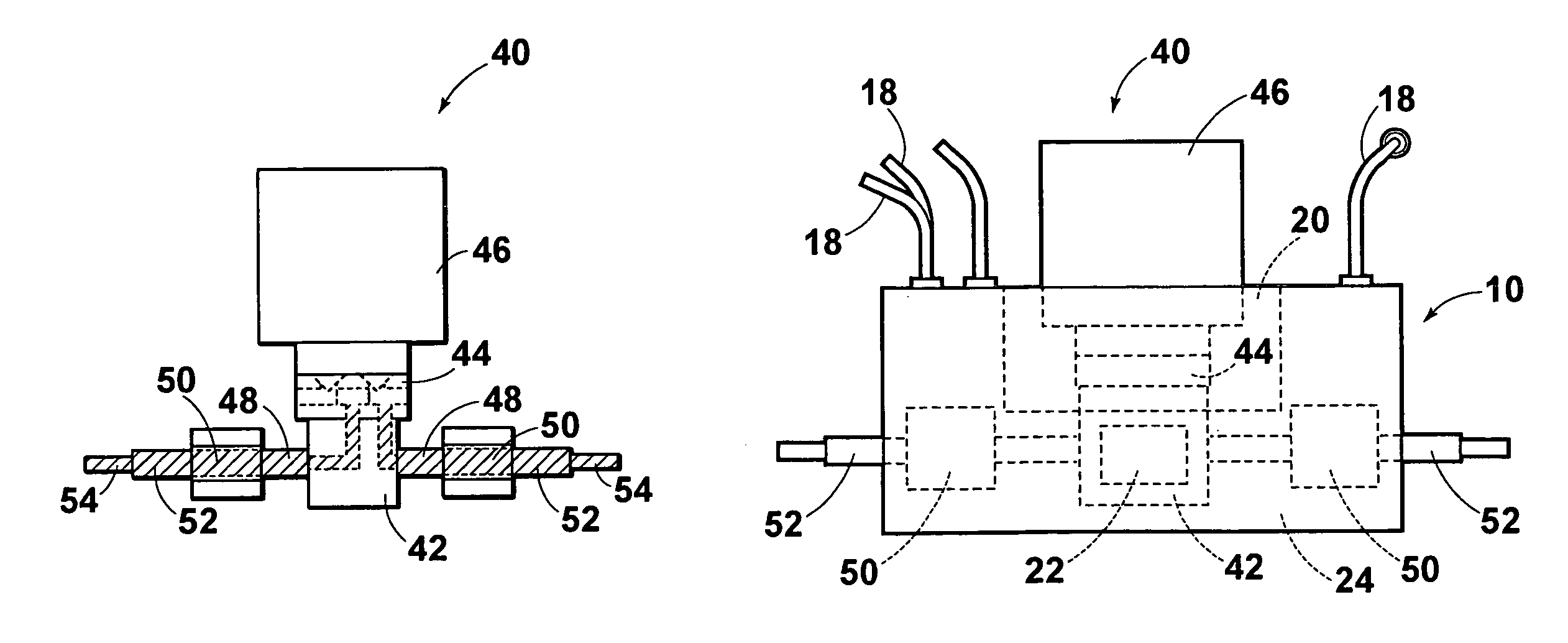
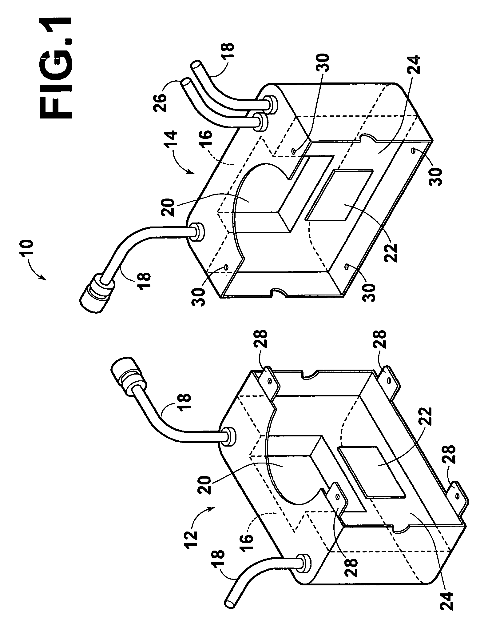
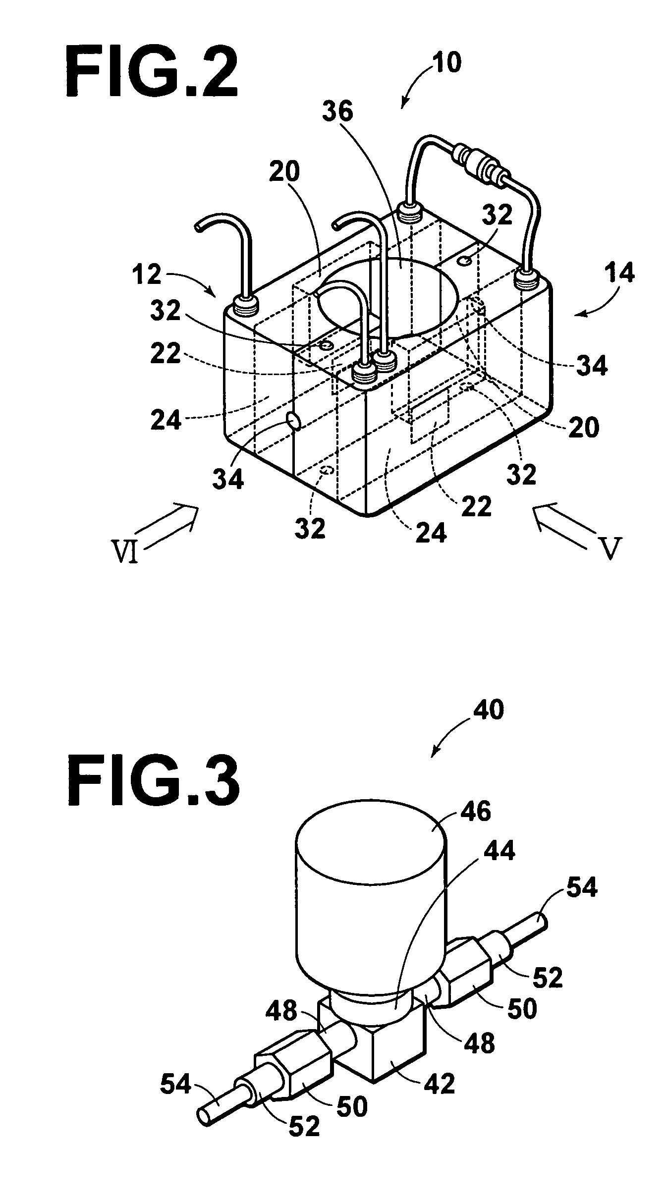
[0023]FIG. 1 is a perspective view of a heater unit 10 according to an embodiment of the present invention illustrating the main body of the unit comprising a pair of housing halves 12, 14 being opened. Each of the pair of housing halves has a built-in ceramic heater 16 along the side wall. Each of the ceramic heaters 16 generates heat when a current is flowed through a lead wire 18 whose both ends are drawn outside. A stainless panel is attached to the inner surface of the ceramic heater 16, forming a flat panel heater. The flat panel heater has a recessed portion 20 at the top to receive the lower portion of the actuator of a valve to be described later. A heat insulating material (not shown) is inserted between the ceramic heater 16 and outer wall of each o...


PUM


Abstract

A heater unit having a main body constructed in the form of a housing and covers the entire flow path forming sections of the valve and joints, and a heater built in the main body is mounted on the valve. The heater includes a direct heating section and a radiant heating section. The direct heating section heats at least a part of the flow path forming sections of the valve through direct contact heating. The radiant heating section heats the inside of the main body of the heater unit by radiant heat.

Description

TECHNICAL FIELD[0001]The present invention relates to a valve mount heater unit to be mounted on a valve connected to a fluid piping system through joints.BACKGROUND ART[0002]For a valve mounted on a piping system that supplies gas to semiconductor manufacturing equipment or the like, it is necessary to prevent formation of dew condensation within the valve due to a temperature drop in the gas as it passes through the valve. In addition, a valve mounted on a piping system that carries liquid that solidifies at a temperature near room temperature, it is necessary to prevent a blockage of the valve or development of accretion within the valve due to solidification of the liquid. Still further, for a piping system that carries high temperature gas or liquid, a temperature drop in the fluid to be carried through the piping system as the fluid passes through the valve is a problem when the fluid needs to be carried through the piping system without any appreciable temperature drop.[0003]...

Claims


Application Information

Patent Timeline
Patent Type & Authority Patents(United States)
IPC IPC(8): H05B1/00F16K49/00F16L53/35
CPCF16K49/00F16L53/005F16L53/35Y10T137/6606
Inventor HIRATSUKA, AKIHIKONOMOTO, TSUGUHIRO
Owner TOKYO TECHNOLOGICAL LABO
Why Eureka
Try Eureka