Switch plate area light

a technology of switch plate and area light, which is applied in the direction of fixed installation, lighting elements, lighting and heating equipment, etc., can solve the problems of inability to discover additional problems, many problems that cannot even be discovered, and extremely long life, so as to achieve the effect of more economic production

Inactive Publication Date: 2010-12-14
NITE IZE INC
View PDF29 Cites 44 Cited by
  • Summary
  • Abstract
  • Description
  • Claims
  • Application Information

AI Technical Summary

Benefits of technology

[0005]However, the present disclosure realizes that multiple LED night lights are neither necessary nor desirable for the following reasons. White light LEDs generally are very efficient and provide a large amount of light for a given amount of current. Having an excessive amount of light emanating from the LED has a detrimental effect on night vision. One needs an adequate amount of light to see the pathway beneath the switch clearly, but no more. Additional LEDs require additional current; thus, there is more heat generated by the electronics to dissipate behind the switch plate. White LEDs are a relatively expensive component compared to the other electronic parts in the LED drive circuitry. The use of one LED allows the device to be produced more economically.

Problems solved by technology

Many issues exist that cannot even be discovered by the basic realization of the need.
Although, this realization addresses the above-identified need, additional problems are discovered through the usage of a return path through the load.
The LED is deliberately driven below its rated input, resulting in extremely long life.
Having an excessive amount of light emanating from the LED has a detrimental effect on night vision.
White LEDs are a relatively expensive component compared to the other electronic parts in the LED drive circuitry.
Another problem discovered is the problem of reactive loads.
Because the load functions as a return path for electrical current, it is important to be able to pass current through the load without a significant amount of impedance, as this will dim the light produced by the LED and may also cause a significant amount of LED flickering.
These use an electronic ballast and so present a more reactive load to the LED driver circuitry.

Method used


Image

  • Switch plate area light
  • Switch plate area light
  • Switch plate area light

Examples


Embodiment Construction

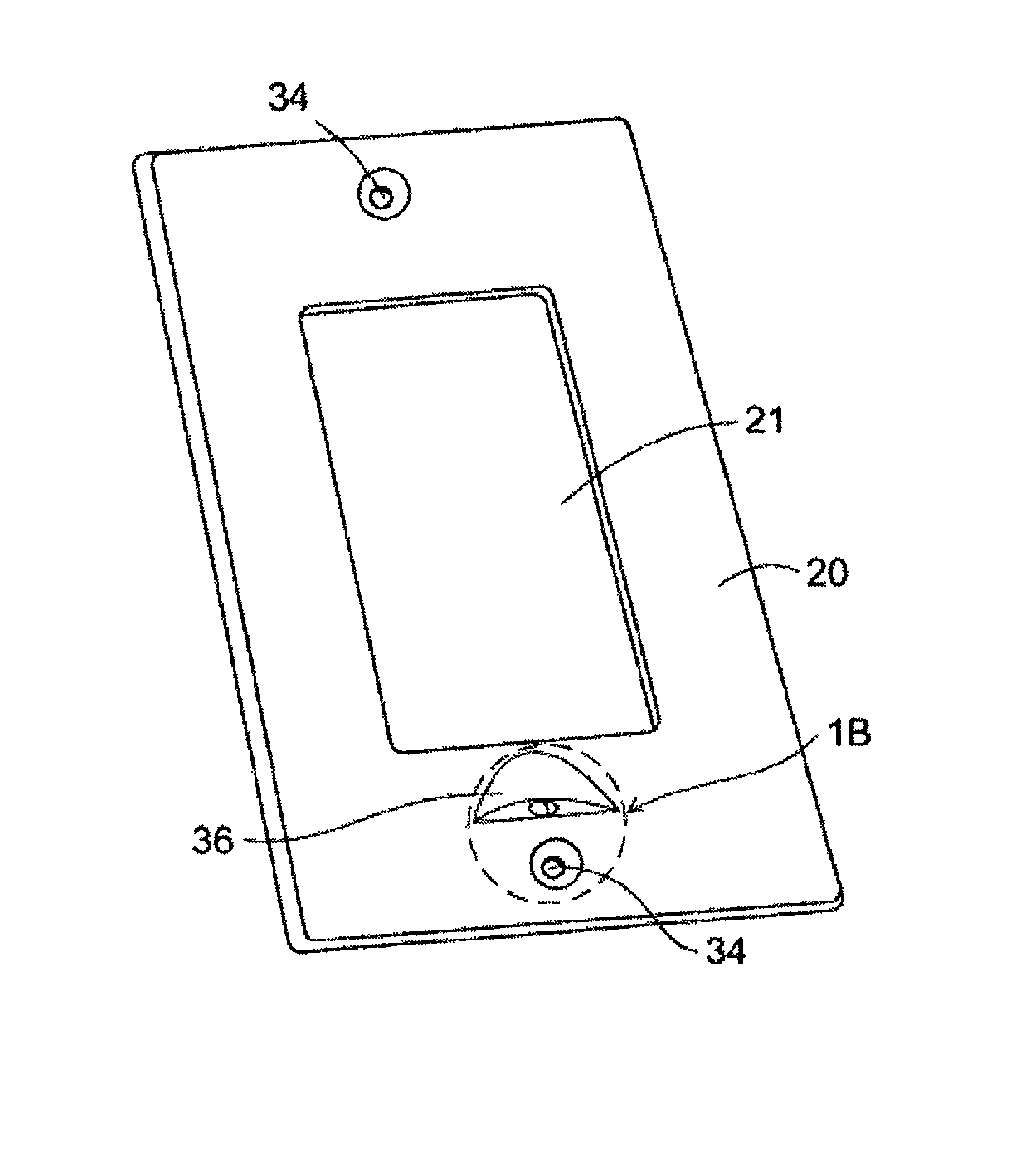
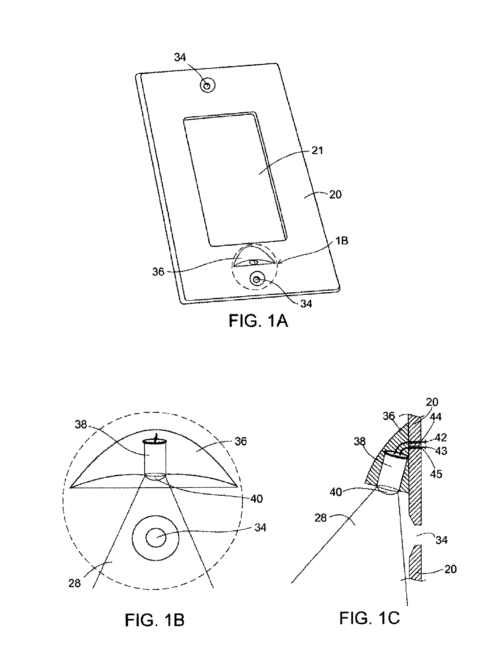
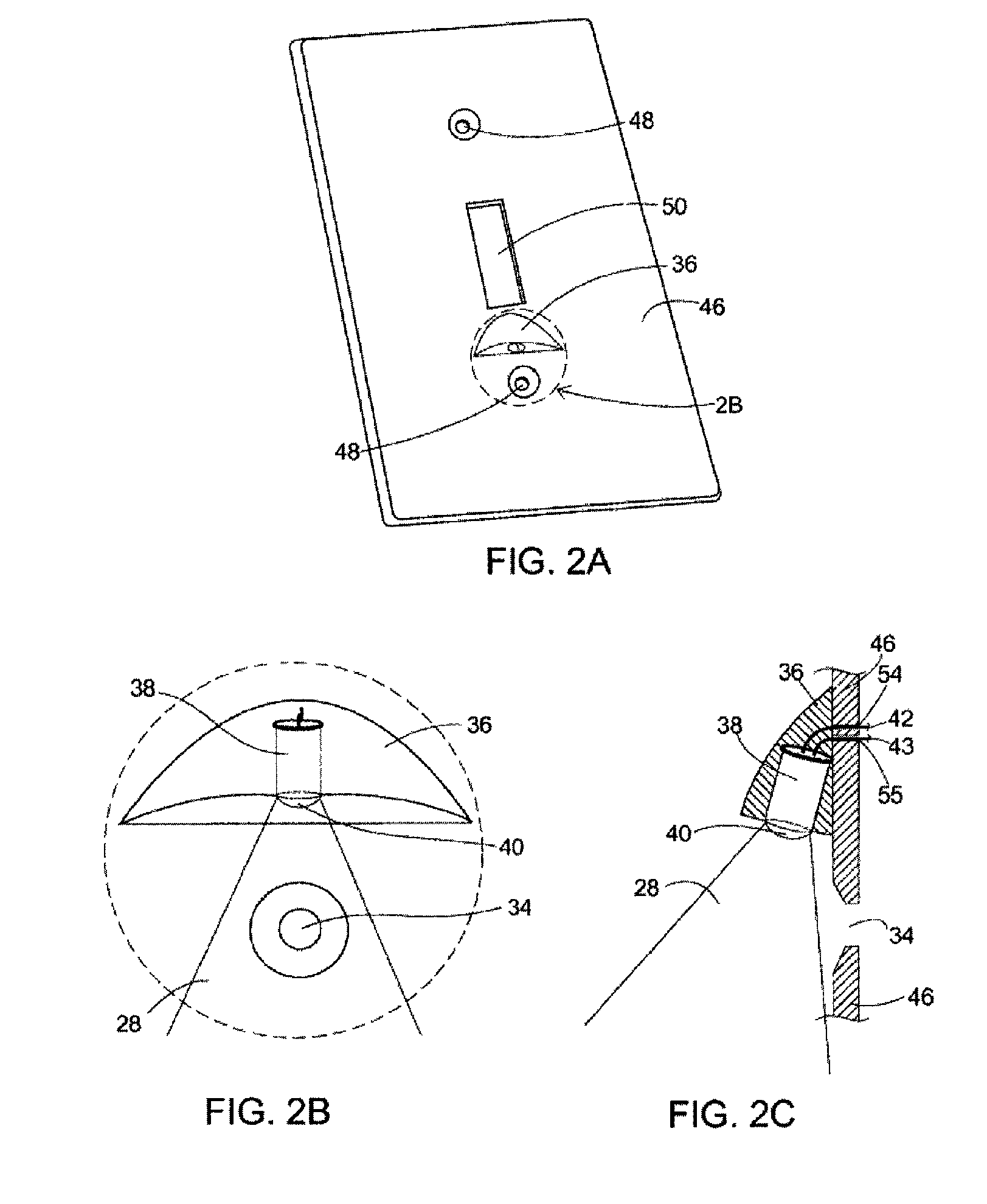
[0033]In the present description, the part numbers refer to the following items:[0034]20 rocker type switch plate[0035]21 hole for protrusion of rocker type switch[0036]28 light rays emanating from LED[0037]34 hole for mounting screw in rocker type switch plate[0038]36 LED housing[0039]38 LED[0040]40 built-in lens portion of LED[0041]42 anode wire from LED[0042]43 cathode wire from LED[0043]44 hole through rocker type switch plate for anode wire of LED[0044]45 hole through rocker type switch plate for cathode wire of LED[0045]46 toggle type switch plate[0046]48 hole for mounting screw in toggle type switch plate[0047]50 hole for protrusion of toggle type switch[0048]54 hole through toggle type switch plate for anode wire of LED[0049]55 hole through toggle type switch plate for cathode wire of LED[0050]60 LED driver circuit assembly[0051]61 connection wire 1 from LED driver circuit assembly[0052]62 connection wire 2 from LED driver circuit assembly[0053]64 2-way switch[0054]65, 66 2-...


PUM


Abstract

A switch plate area light for attachment to an electrical box includes a body having a first aperture adapted to accommodate an element selected from a switch and an outlet, a second aperture adapted to accommodate a screw for attaching the body to the electrical box, and a third aperture located at a light-directing portion of the body. The light further includes a light emitting diode (LED) located in the third aperture, wherein the third aperture is adapted to receive the LED. The light also includes a driver circuit, connected with the LED and mounted on the body, the driver circuit having a pair of wires to be interconnected with the circuitry of the electrical box without the removal of the electrical box, wherein no ground wire is used to connect the driver circuit, and a load borne by the element is not activated when the LED is on.

Description

CROSS-REFERENCE TO RELATED APPLICATIONS[0001]This application is a continuation-in-part of U.S. patent application Ser. No. 11 / 279,904, filed on Apr. 17, 2006, entitled “Switchplate Area Light”, which claims the benefit of provisional U.S. Patent Application No. 60 / 760,626 filed Jan. 21, 2006, all of which applications are incorporated herein by reference.BACKGROUND OF THE INVENTION[0002]Lights oriented on switch plates or socket plates may be found in the art; however, there are many disadvantages to existing designs. In permanently mounted switch plate installations, prior inventors have generally assumed that a neutral wire was available in the outlet box. For purposes of this application, “permanently mounted” means connected directly to the building wiring, not a plug-in device. A neutral wire is always available in electrical boxes containing outlet receptacles. Unfortunately, many times light is needed where no neutral wire is available. This is commonly the case in electrica...

Claims


Application Information

Patent Timeline
Patent Type & Authority Patents(United States)
IPC IPC(8): F21V33/00
CPCH05B33/0803F21S8/035H01H9/18H05B45/34
Inventor GLAZNER, GREGORY F.ORMSBEE, BOWDEN
Owner NITE IZE INC
Why Eureka
Try Eureka