Multi-stage flash evaporator

a flash evaporator and multi-stage technology, applied in multiple-effect evaporation, separation processes, refrigeration components, etc., can solve the problem that the possibilities of increasing the unit capacity of the cross-tube evaporator are only limited, and achieve the effect of reducing temperature differences and associated thermal stresses, and facilitating solution levels control

Inactive Publication Date: 2010-12-14
ALT FRIEDRICH
View PDF14 Cites 10 Cited by
  • Summary
  • Abstract
  • Description
  • Claims
  • Application Information

AI Technical Summary

Benefits of technology

[0011]The main concept of the present invention is a multi stage flash long tube evaporator, comprising a plurality of at least three (3) vertically stacked tiers, each tier comprising a plurality of flash stages and a plurality of at least three (3) parallel arranged tube bundles, each tube bundle being configured to extend in a longitudinal direction through all flash stages of an individual tier. The present invention is aiming to minimize the overall dimensions, foot print, volume and weight of a multi stage flash evaporator, to minimize material quantities required for the manufacturing and the space required in a plant layout. The present invention is aiming in particular to evaporators with medium to large unit capacities in the range from approximately 10 million gallons per day or about 40,000 cubic meters per day to any desired capacity of distillate production, allowing also to be expanded to evaporator unit capacities, significantly larger than the evaporator concepts of prior art.
[0012]The configuration of a multi stage flash long tube evaporator of the present invention allows to divide individual tiers into any number of flash stages as technically and economically feasible, without increasing the evaporator size, which is a significant advantage over a ‘cross tube’ configuration. The increase of number of flash stages leads technically to an increase of the log mean temperature difference on the tube bundles, which in turn allows to reduce the required total tube surface area for a given evaporator capacity and evaporator performance ratio (ratio of mass units of distillate generated per thermal energy unit consumed by a desalination unit, typically in the range of 7-12 lbs / 1000 BTU or approximately 3-5 kg / 1000 kJ).
[0013]The concept of using a plurality of at least three individual tube bundles arranged in parallel in each tier of an evaporator of the present invention, allows to minimize the height of the flash stages compared to an arrangement with only one or two tube bundles traditionally applied to long tube evaporators of the prior art, which leads in combination with the stacked tier configuration to a smaller volume and small foot print of the evaporator compared to a long tube or cross tube configuration of the prior art with medium to large unit capacity.

Problems solved by technology

The cross tube evaporators have technically only limited possibilities to increase the unit capacities beyond the maximum unit capacities of evaporators currently in operation, mainly due to limitations of available tube length for tube bundles.

Method used


Image

  • Multi-stage flash evaporator
  • Multi-stage flash evaporator
  • Multi-stage flash evaporator

Examples


Embodiment Construction

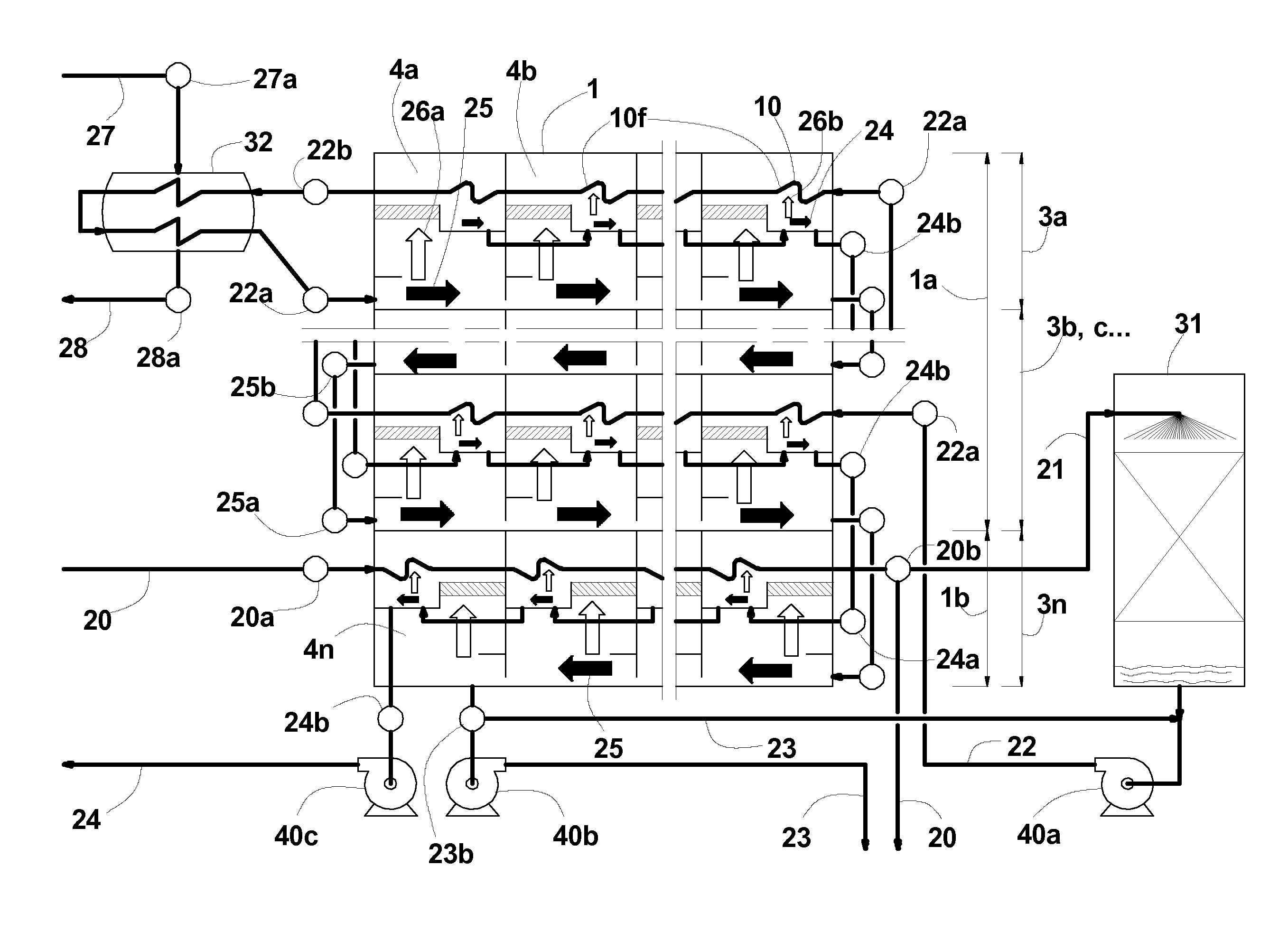
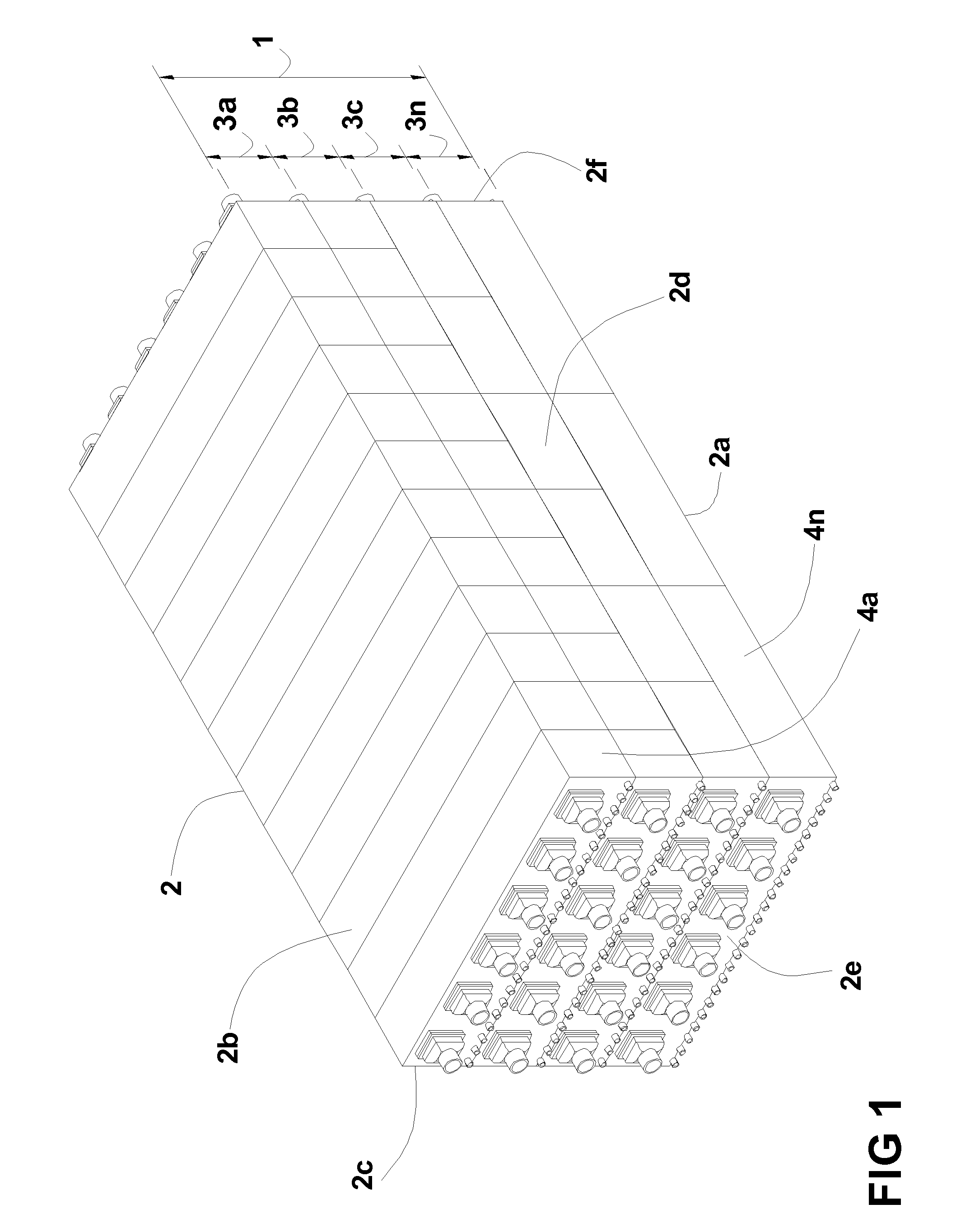
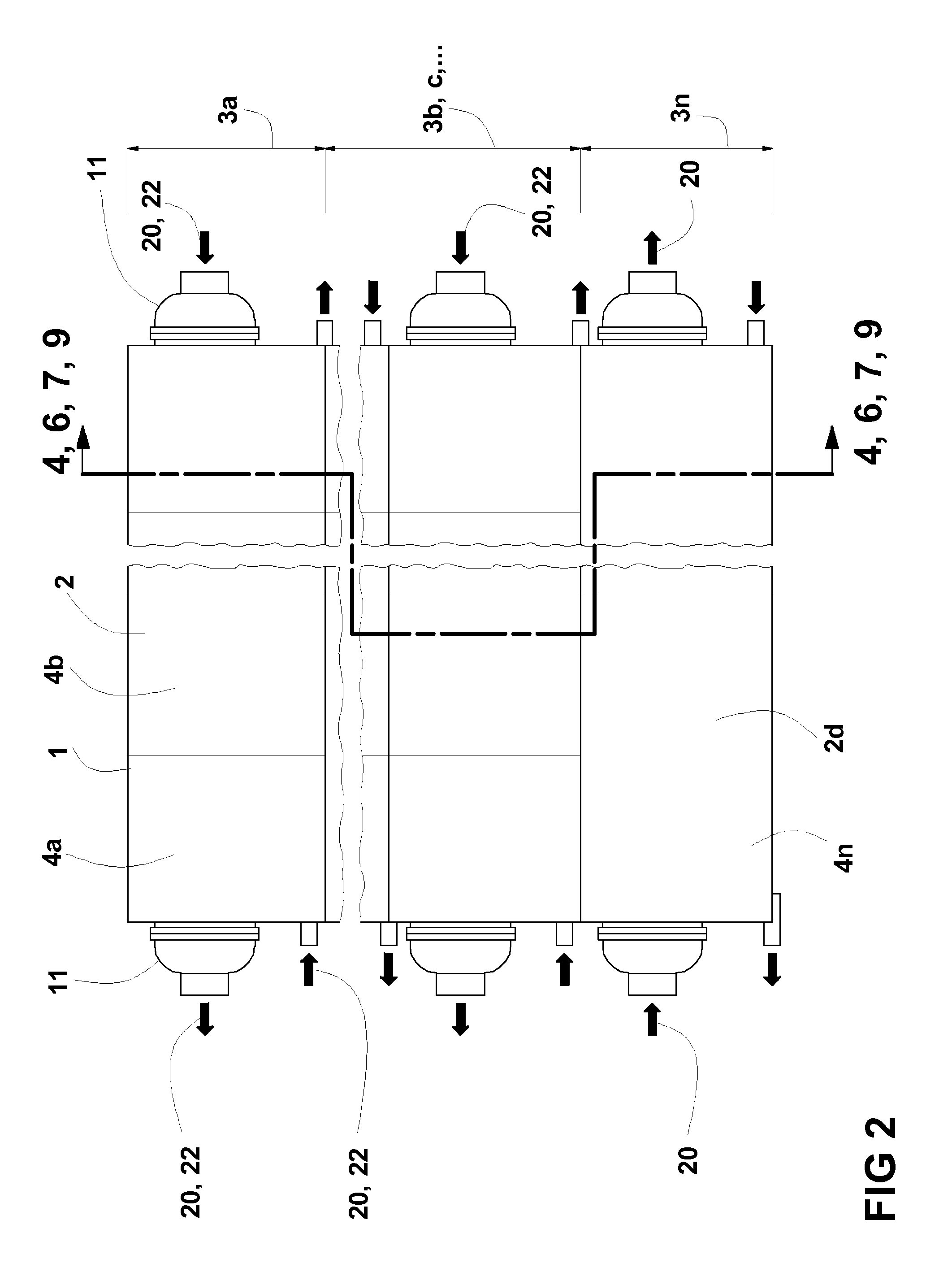
[0038]An example of a multi stage flash long tube evaporator 1 of the present invention is shown in FIG. 1. Details are shown in a right side view FIG. 2, a front view FIG. 3, a cross section FIG. 4 and a longitudinal section FIG. 5. The evaporator 1 comprises a shell 2 with a shell bottom 2a, a shell roof 2b, a left side wall 2c, a right side wall 2d, a front wall 2e and an end wall 2f. The shell 2 is internally divided by a plurality of horizontal tier partitions 6a into a plurality of tiers, with a top tier 3a, at least one intermediate tier 3b or further intermediate tiers 3c . . . and a bottom tier 3n. The horizontal tier partitions 6a are extending substantially in a longitudinal direction of the evaporator 1 from the front wall 2e to the end wall 2f and in a transversal direction from the left side wall 2c to the right side wall 2d. The individual tiers 3a, 3b . . . , 3n are divided by a plurality of flash stage partition walls 6c into a plurality of flash stages, with a firs...


PUM

PropertyMeasurementUnit
shapeaaaaaaaaaa
temperatureaaaaaaaaaa
widthaaaaaaaaaa

Abstract

The present invention provides a multi stage flash long tube evaporator with flash stages arranged in a plurality of at least three tiers, wherein each tier is divided into a plurality of at least two flash stages and a plurality of at least three tube bundles are arranged in parallel and in a longitudinal direction in each tier. This configuration allows to minimize the evaporator shell volume, shell surface, foot print and weight, minimizing the cost of an evaporator and other related plant cost. This configuration is in particular suitable for large evaporator unit capacities.

Description

CROSS-REFERENCE TO RELATED APPLICATIONS[0001]Not Applicable.STATEMENT REGARDING FEDERALLY SPONSORED RESEARCH OR DEVELOPMENT[0002]Not Applicable.REFERENCE TO A SEQUENCE LISTING[0003]Not Applicable.BACKGROUND OF THE INVENTION[0004]A multi-stage flash evaporator is the main component of a seawater desalination plant for producing distilled water from seawater. Most evaporators for large capacity desalination plants are currently of a ‘cross tube’ type with all flash stages arranged in a single tier configuration, being build with evaporator unit capacities up to about 25 million gallons per day or about 100,000 cubic meters per day of distillate production.[0005]A multi-stage flash evaporator comprises a plurality of flash stages, in existing plants typically between 15 and 30. While a heated solution, typically seawater or brine, enters the first flash stage at its highest temperature, the solution flashes down in each consecutive flash stage to a lower temperature compared to the tem...

Claims


Application Information

Patent Timeline
Patent Type & Authority Patents(United States)
IPC IPC(8): B01D3/02B01D3/06B01D3/32
CPCB01D1/04B01D1/26B01D3/065C02F1/06Y10S159/08Y02A20/124
Inventor ALT, FRIEDRICH
Owner ALT FRIEDRICH
Why Eureka
Try Eureka