Fluid sample collection system

a collection system and fluid sample technology, applied in the field of fluid sample collection systems, can solve the problems of increasing the cost and complexity of the analysis process, compromising the integrity of the analysis, and contaminating the sample, so as to reduce the potential loss, minimize the movement of fluid, and minimize the effect of splashing

Active Publication Date: 2010-12-14
CAPITOL VIAL INC
View PDF58 Cites 27 Cited by
  • Summary
  • Abstract
  • Description
  • Claims
  • Application Information

AI Technical Summary

Benefits of technology

[0014]According to another aspect of the present invention, the plunger includes a splash guard that is supported by the handle portion of the plunger. The splash guard is configured to minimize fluid movement into a space defined between the splash guard and the open end of the vial while the absorbent is being compressed against the closed end of the vial. The splash guard minimizes splashing of the buffer and sample mixture as the absorbent is being compressed to express the sample from the absorbent. The splash guard reduces the potential loss of the collected sample through the open end of the vial and also minimizes potential contamination of the sample during the sample collection process.

Problems solved by technology

However, it will be appreciated that if the swab is not sufficiently compressed in the vial by the technician to express the sample from the swab, the integrity of the analysis may be compromised.
Moreover, requiring the technician performing the analysis to extract the sample from the swab generally increases the cost and complexity of the analysis process and also risks contamination of the sample while the collection stick is being handled.

Method used


Image

  • Fluid sample collection system
  • Fluid sample collection system
  • Fluid sample collection system

Examples


Embodiment Construction

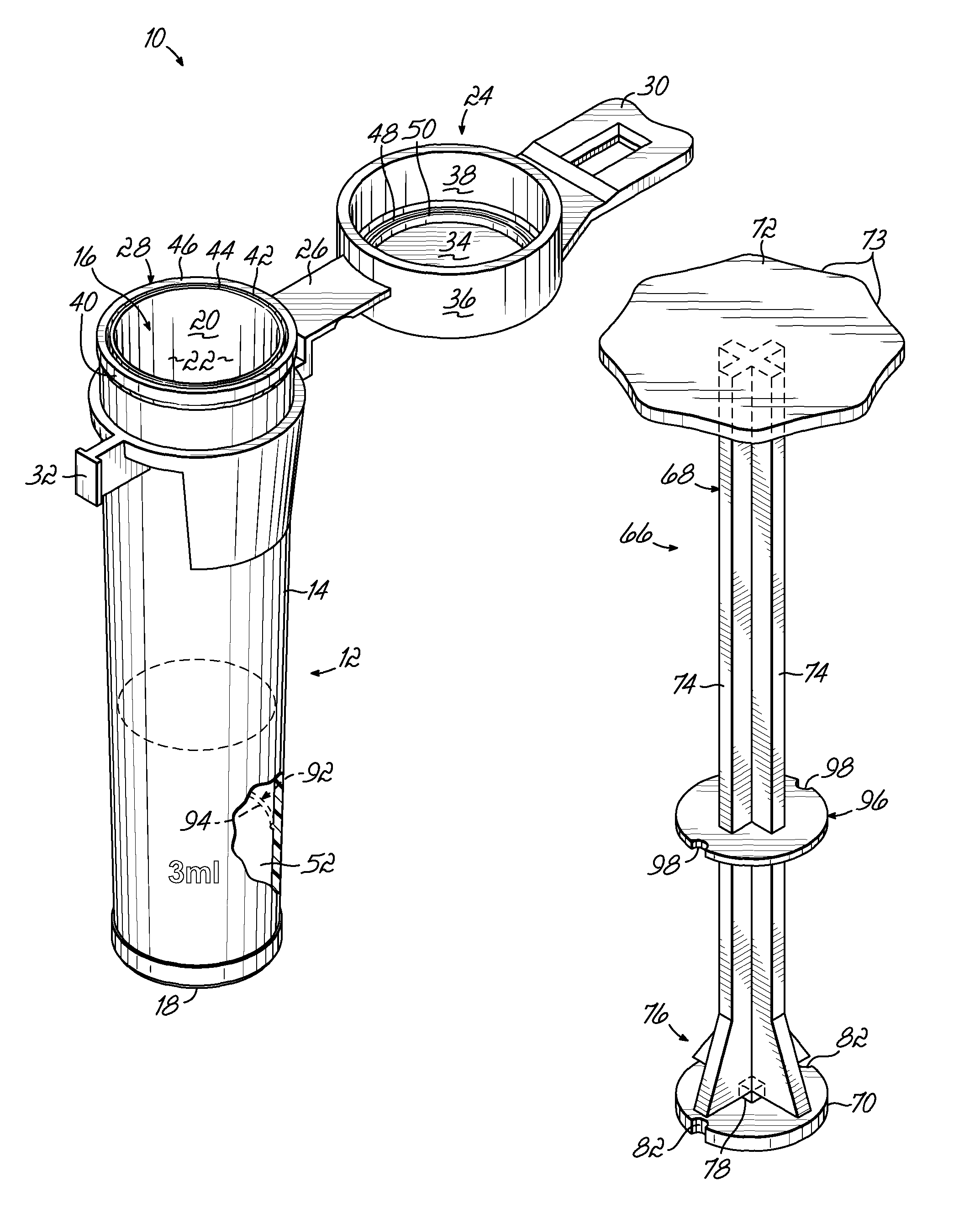
[0024]Referring now to the figures, a fluid sample collection system or kit 10 according to one embodiment of the present invention is shown for collecting and transporting a fluid sample for diagnostics testing. By way of example, the fluid sample may comprise saliva, blood, urine, surface moisture from any type of surface including an exterior body surface, or any other type of fluid that is typically subjected to diagnostics testing. For example, the sample collection kit 10 can be used in applications such as “drugs of abuse” testing, hormone replacement therapy, other diagnostics and clinical testing including HIV screening, environmental sampling, veterinarian sample collection and other similar applications.

[0025]As shown in FIG. 1, the sample collection kit 10 includes a vial 12 having a vial wall 14 that defines an open end 16, a closed end 18, and an interior surface 20 extending between the open and closed ends 16, 18 of the vial to form a vial cavity 22. In one embodimen...


PUM

PropertyMeasurementUnit
temperatureaaaaaaaaaa
inner diameteraaaaaaaaaa
axial heightaaaaaaaaaa

Abstract

A fluid sample collection system includes a vial, a plunger and a fluid sample collection device having an absorbent for absorbing and retaining a fluid sample therein. The plunger includes an elongated handle portion and a plunger head portion detachably connected to the handle portion. The plunger also includes a splash guard supported on the handle portion. During the sample collection process, the saturated absorbent from the sample collection device is placed into the vial and the plunger is then advanced toward a closed end of the vial to express the fluid sample from the absorbent. The plunger head portion is retained within the vial with the absorbent in a generally compressed state and the handle portion is detached and removed from the vial.

Description

FIELD OF THE INVENTION[0001]The present invention relates generally to sample collection systems and, more particularly, to a sample collection system for collecting and transporting a fluid sample.BACKGROUND OF THE INVENTION[0002]Fluid samples are often collected for diagnostics testing including, by way of example, “drugs of abuse” testing, hormone replacement therapy, other diagnostics and clinical testing including HIV screening, environmental sampling, veterinarian sample collection and other similar applications. The substances collected are varied and include, for example, bodily fluids such as saliva, blood, urine, surface moisture from any type of surface including exterior body surfaces, or any other type of fluid that is typically subjected to diagnostics testing.[0003]It is a common practice to use a swab of absorbent material as a collection medium. The swab is often mounted on an end of a collection stick and is supplied in a kit that also contains a container or vial ...

Claims


Application Information

Patent Timeline
Patent Type & Authority Patents(United States)
IPC IPC(8): B01L99/00B01L3/02B01L3/00
CPCB01L3/5029G01N1/10A61B10/0045Y10T436/25375A61B19/42B01L3/5082B01L2300/0618B01L2400/0478B01L2400/0481G01N2001/028Y10T436/2575Y10T436/2525Y10T436/25Y10T436/255A61B10/0096A61B90/05
Inventor GALLAGHER, TIMOTHY JOSEPHSTEIGER, JEFFREY H.HANNE, ROBERT
Owner CAPITOL VIAL INC
Why Eureka
Try Eureka