Impact pad for metallurgical vessels

a technology for impact pads and metallurgical vessels, which is applied in the direction of manufacturing converters, furnaces, manufacturing tools, etc., can solve the problems of high wear in this region, affecting the quality of metallurgical products, and requiring significant labor and downtime for casting wall protectors, so as to minimize the splashing of molten metal, reduce the wear of the vessel, and minimize the effect of turbulence in molten metal

Inactive Publication Date: 2008-12-23
NORTH AMERICAN REFRACTORIES
View PDF48 Cites 3 Cited by
  • Summary
  • Abstract
  • Description
  • Claims
  • Application Information

AI Technical Summary

Benefits of technology

[0010]An advantage of the present invention is the provision of an impact pad for controlling the flow of molten metal poured into a metallurgical vessel to reduce wear to the vessel.
[0011]Another advantage of the present invention is the provision of an impact pad that minimizes splashing of molten metal poured into a metallurgical vessel.
[0012]A still further advantage of the present invention is the provision of an impact pad that minimizes turbulence in molten metal poured into a metallurgical vessel.
[0013]Still another advantage of the present invention is the provision of an impact pad that eliminates the need to use higher quality and / or thicker bricks in the lining of a metallurgical vessel in order to reduce wear thereto.
[0014]Yet another advantage of the present invention is the provision of an impact pad that reduces wear to a metallurgical vessel at less cost and with less time consumption than prior art approaches for reducing wear.
[0015]These and other advantages will become apparent from the following description of a preferred embodiment taken together with the accompanying drawings and the appended claims.

Problems solved by technology

High wear occurs in this region due to splashing and turbulence of the molten metal as it hits the impact pad.
In this regard, providing a raised or thicker impact area in the bottom of the ladle may increase the life of the impact pad, but it does not provide protection for the ladle side wall.
Casting wall protectors requires significant labor and downtime to set a form, cast and set the castable material, and remove the form following setting of the castable material.
Domed and pyramid shaped impact pads may redirect flow of the molten metal to other regions of the ladle, but do not minimize turbulence.
Consequently, wear may simply occur in a different region of the ladle.
Using higher quality and / or thicker bricks for the side wall requires additional expense that does not address the underlying cause of the wear problem.

Method used


Image

  • Impact pad for metallurgical vessels
  • Impact pad for metallurgical vessels
  • Impact pad for metallurgical vessels

Examples


first embodiment

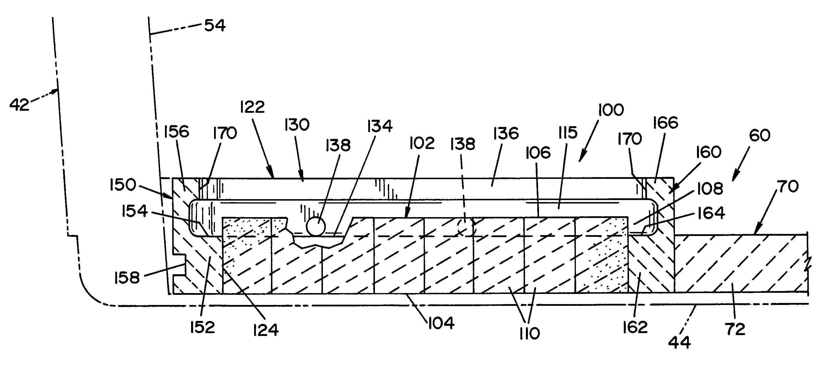
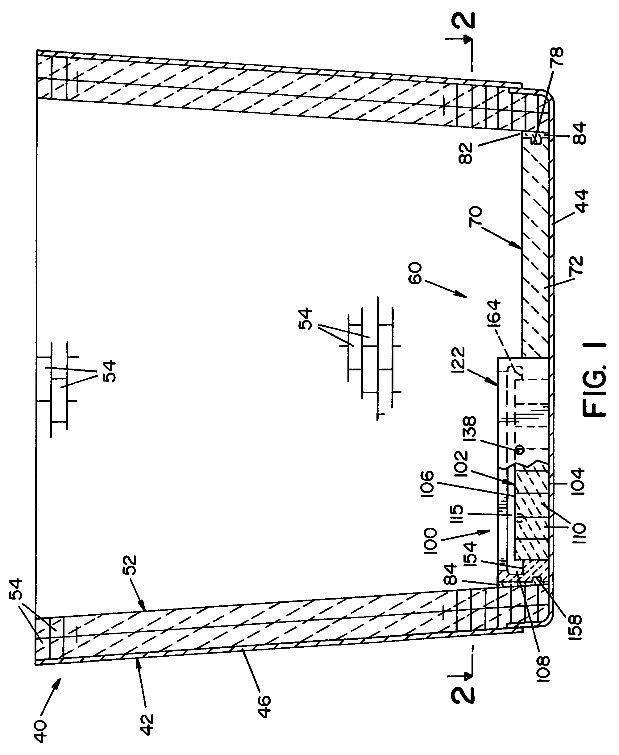
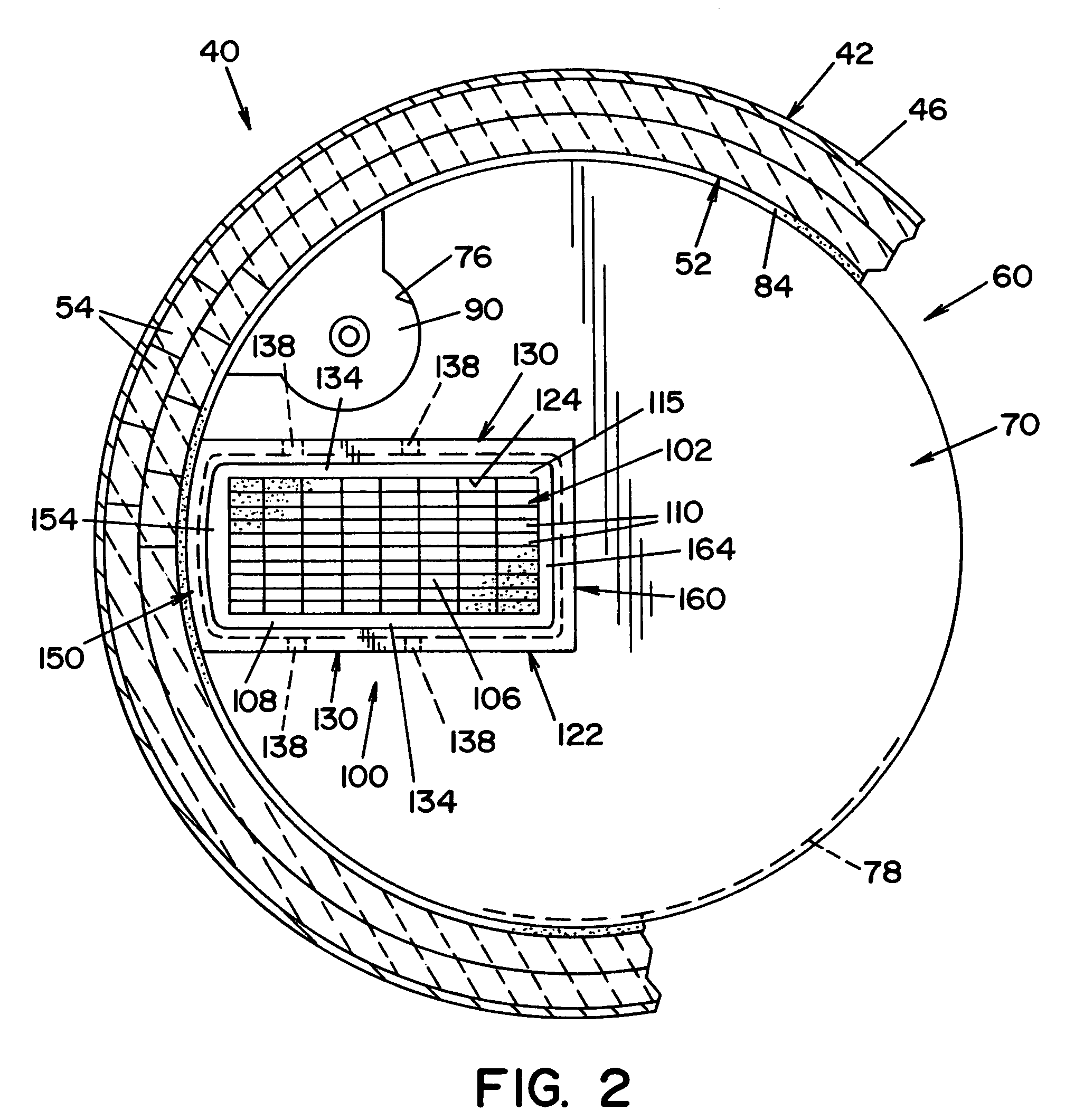
[0031]A bottom lining 60 (best seen in FIG. 3) is adapted to be disposed on bottom 44 of ladle 40 within refractory lining 52. Bottom lining 60 is basically comprised of an impact pad 100, according to the present invention, embedded within a monolithic, refractory slab 70 of refractory material 72. Bottom lining 60 may be “pre-formed” or “cast-in-place”. With respect to a “pre-formed” bottom lining 60, impact pad 100 is pre-formed in a first mold and then placed into a second mold (not shown) to cast slab 70 in place around impact pad 100. After curing and setting, bottom lining 60 is removed from the second mold and placed within bottom 44 of ladle 40 as a pre-assembled unitary component. With respect to a “cast-in-place” bottom lining 60, impact pad 100 is preferably pre-formed outside of ladle 40 and then placed in bottom 44 of ladle 40. Thereafter, slab 70 is cast around impact pad 100 inside ladle 40. Bottom lining 60 is shown and described in the illustrated embodiment as a “...

second embodiment

[0047]Referring now to FIGS. 6-8, the present invention is shown. Impact pad 200 is similar in most respects to impact pad 100. However, frame portion 222 of impact pad 200 includes a rear wall 250 having an upper section 256 that extends further upward than upper section 156 of rear wall 150 of impact pad 100. Accordingly, rear wall 250 has a height that is greater than the height of side walls 130 and front wall 160. Like rear wall 150 of impact pad 100, rear wall 250 is curved to match the profile of refractory lining 52 disposed along the inner surface of side wall 46. The increased height of rear wall 250 provides additional protection to refractory lining 52 from splashing of molten metal. As best seen in FIG. 8, upper section 256 has a sloped front face 257 for directing molten metal toward interior cavity 115.

[0048]In the embodiment of the present invention shown in FIGS. 6-8, the increased height of rear wall 250, as compared to rear wall 150, provides additional protection...

third embodiment

[0049]FIGS. 9-10 illustrate the present invention. Impact pad 300 has a bottom wall portion 302 comprised of differently sized refractory bricks 110 arranged in an upright, soldiered configuration. In this regard, different sizes of bricks 110 are arranged to form bottom wall portion 302 having multiple sections, designated 302a, 302b, and 302c that form a stepped configuration. Bottom wall portion 302 has an upper surface comprised of surfaces 306a, 306b and 306c that correspond respectively to sections 302a, 302b and 302c. Bottom wall portion 302 has a generally planar lower surface 304. Upper section 166 is omitted from front wall 160, thus providing an opening 118 for the flow of molten metal out of interior cavity 115, as it descends the stepped configuration of bottom wall portion 302.

[0050]In the embodiment of the present invention shown in FIGS. 9-10, the stepped configuration of bottom wall portion 302 guides molten metal toward the center of ladle 40. In this regard, molte...


PUM

PropertyMeasurementUnit
densityaaaaaaaaaa
melting temperatureaaaaaaaaaa
temperatureaaaaaaaaaa

Abstract

An impact pad for a bottom lining of a metallurgical vessel, such as a ladle. The impact pad reduces wear to side walls of the metallurgical vessel by controlling the flow of an incoming stream of molten metal to minimize splashing and turbulence. The impact pad includes a frame portion and a bottom wall portion. The frame portion and bottom wall portion define an interior cavity for receiving the stream of molten metal.

Description

FIELD OF THE INVENTION[0001]The present invention relates generally to an impact pad for a metallurgical vessel, and more particularly to an impact pad that reduces wear to the wall of a metallurgical vessel by controlling the flow of an incoming stream of molten metal to minimize splashing and turbulence. The present invention is particularly applicable for use in ladles used in handling molten steel, and will be described with particular reference thereto.BACKGROUND OF THE INVENTION[0002]Molten metal, in particular molten steel, is often poured from one metallurgical vessel to another. For example, molten metal may be poured from a furnace into a ladle, and then from a ladle into a tundish and from a tundish into a mold. Ladles typically have a generally horizontal or flat circular bottom with a vertically arranged side wall, sometimes referred to as a “barrel.” The bottom and side wall have a lining made of refractory materials. It is known to use impact pads to try to control th...

Claims


Application Information

Patent Timeline
Patent Type & Authority Patents(United States)
IPC IPC(8): C21C5/44
CPCB22D41/003
Inventor BARRETT, RONALD
Owner NORTH AMERICAN REFRACTORIES
Why Eureka
Try Eureka