A side spray method for cooling the steel strip after hot rolling

a technology of hot rolling and steel strips, applied in the field of metalurgical technology, can solve the problems of uneven cooling, poor cooling, uneven cooling, etc., and achieve the effects of preventing backsplash and backflow, reducing splashing, and improving uniform cooling

Active Publication Date: 2021-03-18
BAOSHAN IRON & STEEL CO LTD
View PDF1 Cites 3 Cited by
  • Summary
  • Abstract
  • Description
  • Claims
  • Application Information

AI Technical Summary

Benefits of technology

[0051]The present invention minimizes splash caused by intense collision between high pressure side spray water and residual water on the surface of the steel strip by using a guided water-jet side spray device and side spray water collecting device. While breaking the steam film on the surface of the steel strip, the residual water on the surface of the steel strip can be swept into the collecting device by using the water fall of three-dimensional curved surface, which can be used for different width of the steel strip, and introduced into the drainage ditch to prevent backsplash and backflow to the roller table and surface of steel strip, so as to improve the uniformity of cooling. The anti-collision design of side spray collecting device not only protects the collecting device but also prevents the end of steel strip from being stuck in steel scrap. Uniform cooling can be achieved by side spray devices in staggered arrangement and in a mode of open-in-pairs.
[0052]FIG. 1 is a schematic diagram of the cooling arrangement of the hot-rolled steel strip after rolling of the present invention.
[0053]FIG. 2 is a schematic structural diagram of the side spray device of the present invention.
[0054]FIG. 3 is a schematic diagram of the side spray water collecting device of the present invention.
[0055]FIG. 4 is a schematic diagram of a single nozzle side spray of the present invention. In-picture marking: α—direction angle; β—incident angle; θ—scattering angle; h—height of nozzle from nozzle; L—watermark length; Ws—water spray coverage of the side spray; Wg—width of the roller table.
[0056]FIG. 5 is a schematic diagram of the effect of the guided side spray of the present invention.

Problems solved by technology

The cooling water of each tilting frame falls on the upper surface of the steel strip in a disorderly flow state that is not effectively excluded, and form residual water on the surface resulting in uneven cooling.
At the same time, due to the rapid movement of the steel strip, part of the cooling water will rush into the adjacent tipping rack area as the steel strip advances, destroying its cooling water state and resulting in poor cooling and uneven cooling.
The cooling water will form a steam film when it encounters a high-temperature steel plate, hindering the direct contact of subsequent cooling water with the steel plate and affecting the cooling efficiency.
The effect of removing water and breaking the steam film, but the following problems exist in the actual use process:1) Side spray water splash causes adverse effects
The lateral spray dewatering will inevitably cause a violent collision between the side spray water and the residual water, which will generate a large amount of splash water, especially near the area of the nozzle, the collision is more intense and the splash water is high and far that affects the surrounding environment.
In addition, a large amount of splashing water can cause malfunctions of electrical equipment such as motors, making some production lines forced to stop or rarely turn on the side spray at the motor, resulting in uneven cooling on both sides of the steel strip.
At the same time, the residual water with a certain impact force when sprayed laterally is easy to cross the water wall and enter the front of the strip, resulting in uneven cooling surface.
Since baffles are provided on both sides of the cooling roller table, it will cause backsplash and backflow after the lateral water spray collides with the baffle.
It is difficult to remove the side spray water quickly.
The backsplash and backflow to the surface of the steel strip not only affects the side spray effect, but also causes uneven cooling.2) It is difficult to take into account the water removal effect of different width steel strips
Lateral side spray, especially the lateral side spray of cylindrical nozzles, it is difficult to set an optimal contact point (spray point) between the spray water and the surface of the steel strip.
There are many specifications of hot-rolled steel strips, and the wide and narrow steel strips bring great difficulty to the selection of spray points.
The side spray points are very close to the side, and the narrow steel strip cannot be swept to the surface; the side spray points are very close to the middle, the edges of the broadband steel cannot be effectively purged.
In addition, the cylindrical nozzle will also cause the area of the spray point to be too cold, making the widthwise cooling uneven.
The actual effect is not good.
For wider steel strips, it is different to sweep residual water out of the steel strip surface due to insufficient subsequent power of spraying water; for steel strip with bad shape and warping, the spraying water can not only sweeps the surface of the steel strip but also causes the steel strip to deviate.
Although the side spray can cover the entire width, when the amount of residual water is large and the impact is strong, the lateral side spray is not very effective in removing water, and the side spray and the laminar water collide violently, which will causes a lot of splashes, and not only easy to cause peripheral electrical equipment failure, but also affects the surrounding environment.
The utility model does not clarify the structure of the high-pressure water side spray device, so it is doubtful whether it can adapt to the purge of steel plates of different widths; the utility model adopts high-pressure water spray and gas spray, which will inevitably causes side water spray, gas and residual water to collide violently, generate a large amount of splash water, and it is difficult to enter the negative pressure water suction system completely, which will causes damage to surrounding electrical equipment and the environment; side spray devices need to be equipped with both air supply, water supply and water pumps that are too complex and expensive.
The patent only adds a pair of side nozzles in front of the thermometer, and does not solve the adverse effect of residual water on the cooling of the entire length of the cooling zone; adding side spray nozzles can effectively increase the water removal effect, but excessive temperature drop of side spray nozzles can adversely affect the cooling control of strip, and large amount of side spray splashes can also affect the electrical equipment and surrounding environment.
The rectangular collecting port of the device is too large without anti-collision design.
When the head of the steel strip is deviated, it is easy to clamp into the collecting port, resulting in steel scrap.
Although the above patents have improved the original side spray effect to some extent, they cannot effectively solve the problem that the side spray water and the residual water violently collision with the splash caused by the lateral spray and affect the surrounding environment and electrical equipment.
Some devices have security risks, and some devices are too complicated.

Method used


Image

  • A side spray method for cooling the steel strip after hot rolling
  • A side spray method for cooling the steel strip after hot rolling
  • A side spray method for cooling the steel strip after hot rolling

Examples


example 1

[0072]The width of the roller table can be a variety of widths, such as 1050 mm, 1250 mm, 1350 mm, 1450 mm, 1580 mm, 1700 mm, 1800 mm, 1880 mm, 2050 mm, 2250 mm, 2300 mm, but not limited thereto.

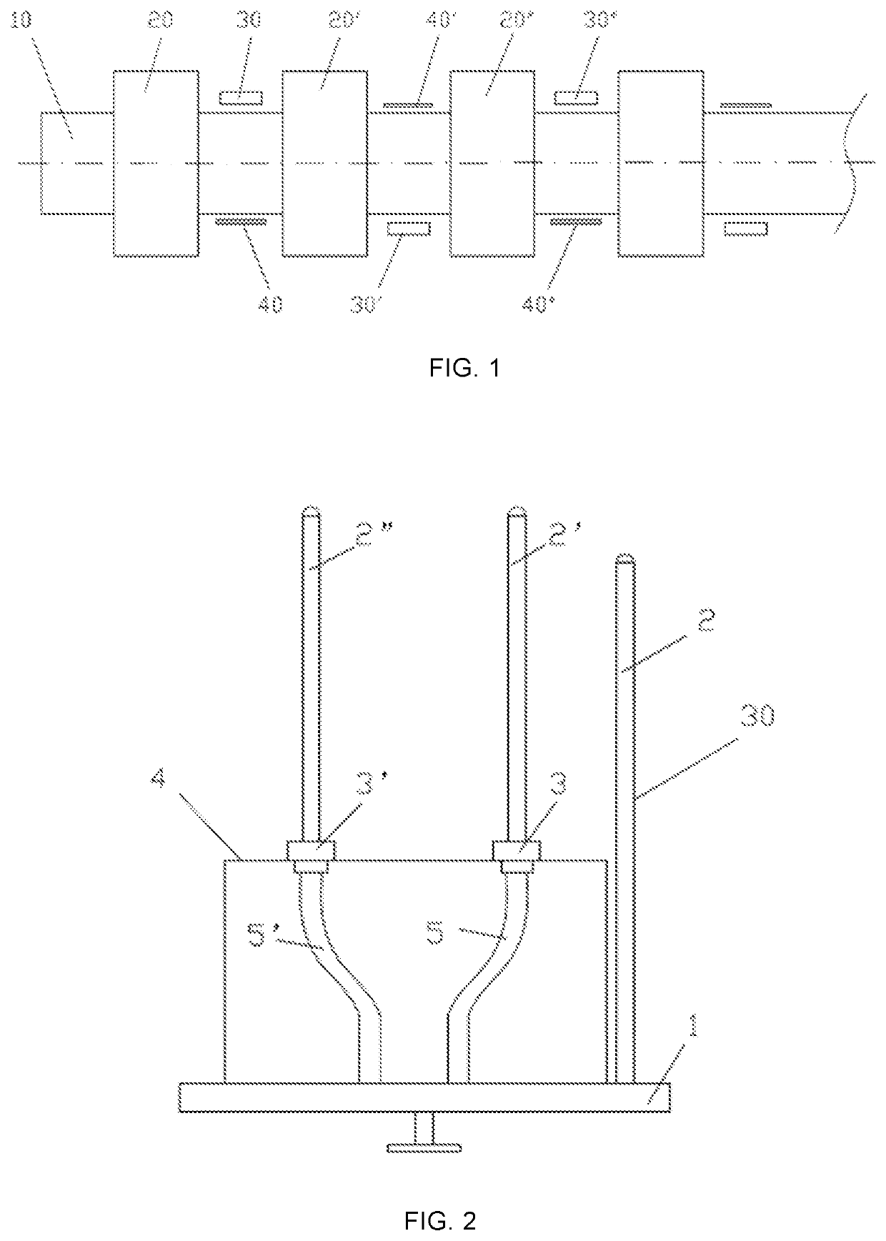
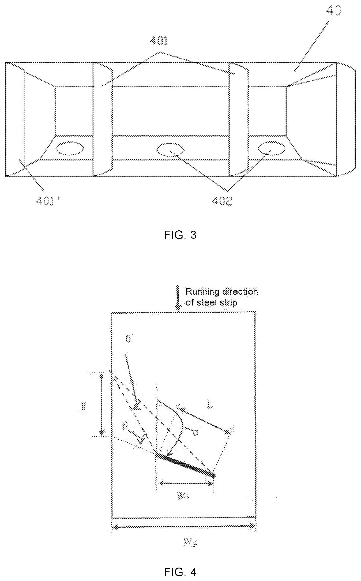
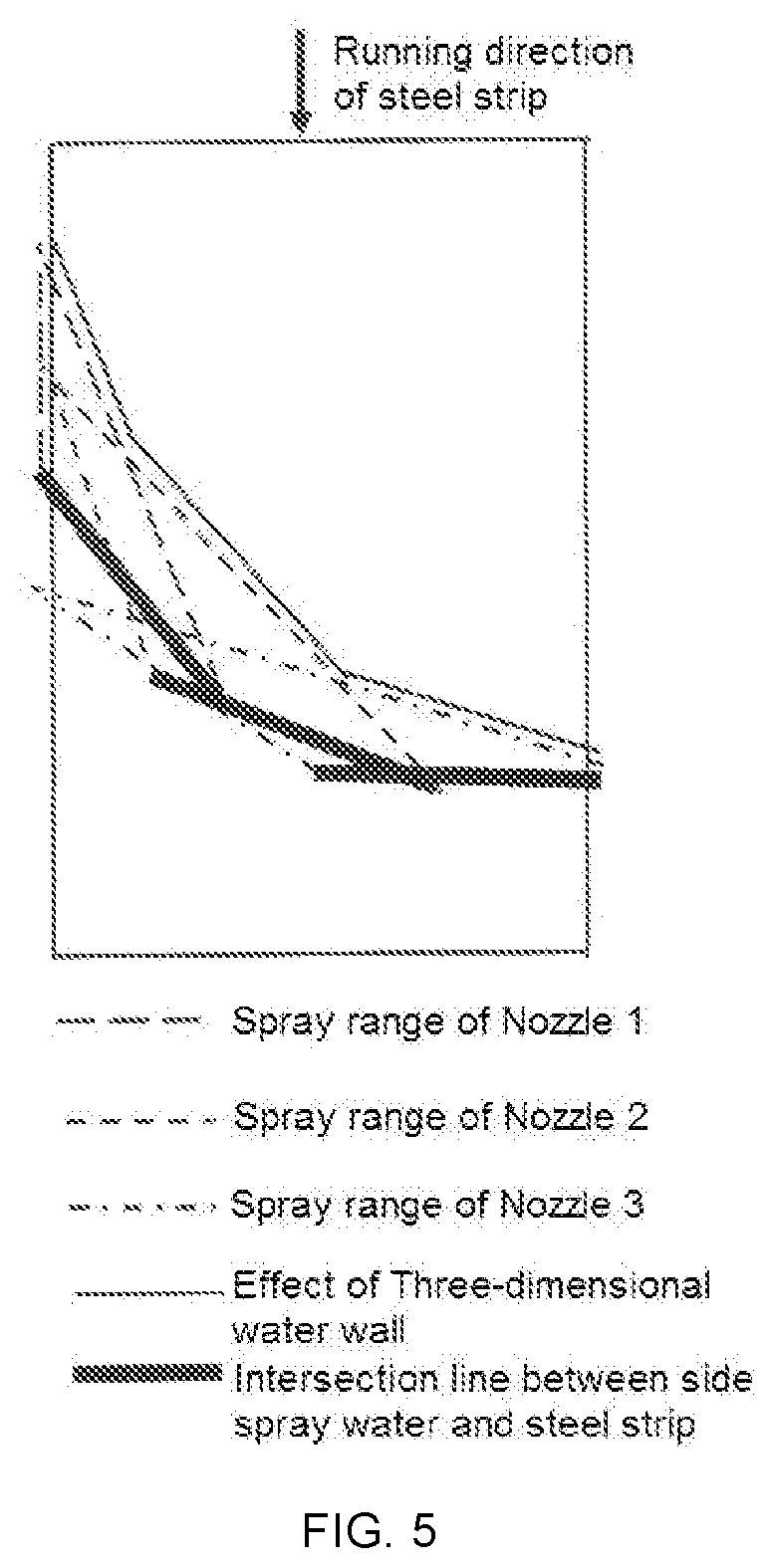
[0073]Take a width of the roller table with 1800 mm cooling zone of hot-rolling line as an example.[0074](1) The side spray device is designed with three side spray tubes, that is three nozzles, each nozzle should cover at least the roller table range on the width direction Ws=1800 mm / 3=600 mm.[0075](2) According to the principle of guided side spray, the 1st nozzle's direction angle is set to 150°, and the watermark length on the surface of the steel strip is L1:[0076]L1=600 / sin(180°−150°)=1200 mm,[0077]2nd nozzle's direction angle is set to 135°, and the distance to 1st nozzle is S1:[0078]S1=600 / tan(180°−150°)−600 / tan(180°−135°)=439 mm,[0079]Watermark length L2 of 2nd nozzle on the steel strip surface:[0080]L2=600 / sin(180°−135°)=848.5 mm,[0081]3rd nozzle mainly plays a strong sweeping func...

example 2

[0102]Take a width of the roller table with 1050 mm cooling zone of hot-rolling line as an example.

[0103](1) The side spray device is designed with three side spray tubes, that is three nozzles, each nozzle should cover at least the roller table range on the width direction Ws=1050 mm / 3=350 mm.

[0104](2) According to the principle of guided side spray, 1st nozzle's direction angle is set to 165°, and the watermark length on the surface of the steel strip is L1:

[0105]L1=350 / sin(180°−165°)=1352 mm,

[0106]2nd nozzle's direction angle is set to 150°, and the distance to 1st nozzle is S1:

[0107]S1=350 / tan(180°−165°)−350 / tan(180°−150°)=700 mm,

[0108]Watermark length L2 of 2nd nozzle on the steel strip surface:

[0109]L2=350 / sin(180°−150°)=700 mm,

[0110]3rd nozzle mainly plays a strong sweeping function, the direction angle is set to 105°, and the distance to 2nd nozzle is S2:

[0111]S2=350 / tan(180°−150°)−350 / tan(180°−105°)=512 mm,

[0112]Watermark length L3 of 3rd nozzle on the steel strip surface:

[...

example 3

[0131]Take a width of the roller table with 2250 mm cooling zone of hot-rolling line as an example.

[0132](1) The side spray device is designed with three side spray tubes, that is three nozzles, each nozzle should cover at least the roller table range on the width direction Ws=2250 mm / 3=750 mm.

[0133](2) According to the principle of guided side spray, 1st nozzle's direction angle is set to 135°, and the watermark length on the surface of the steel strip is L1:

[0134]L1=750 / sin(180°−135°)=1061 mm;

[0135]2nd nozzle's direction angle is set to 110°, and the distance to 1st nozzle is S1:

[0136]S1=750 / tan(180°−135°)−750 / tan(180°−110°)=477 mm,

[0137]Watermark length L2 of 2nd nozzle on the steel strip surface:

[0138]L2=750 / sin(180°−110°)=798 mm,

[0139]3rd nozzle mainly plays a strong sweeping function, the direction angle is set to 75°, and the distance to 2nd nozzle is S2:

[0140]S2=750 / tan(180°−110°)+750 / tan(75°)=474 mm,

[0141]Watermark length L3 of the 3rd nozzle on the steel strip surface:

[014...


PUM

PropertyMeasurementUnit
direction angleaaaaaaaaaa
heightaaaaaaaaaa

Abstract

Aside spray method for cooling the steel strip after hot rolling, comprising the following steps: a) providing side spray devices (30, 30′, 30″) behind each of cooling sections after hot rolling (20, 20′, 20″), the side spray devices being staggered along the two sides of an run out roller table (10), each side spray device comprising at least two spray units, each spray unit comprising spray tubes (2, 2′, 2″) and nozzles on the tubes, the spray tubes being in parallel and vertically arranged along running direction of the steel strip, the covering ranges of adjacent nozzles are partially overlapped, and a total spray coverage of nozzles covers the width of the entire run out roller table; side spray water collecting devices (40, 40′, 40″) are provided on the other side of the run out roller table that is opposite to side spray devices, so that side spray water being collected by the water collecting devices; b) controlling the side spray devices in a mode of open-in-pairs, i.e., side spray devices on either side of the run out roller table must be started simultaneously. The side spray method can effectively purge the residual water on the surface of steel strip having different width specifications, improves the cooling uniformity, and reduces splashes as far as possible to avoid adverse effects on the environment and electrical equipment.

Description

TECHNICAL FIELD[0001]The present invention belongs to metallurgical technology and relates specifically to a side spray method for cooling the steel strip after hot rolling.BACKGROUND ARTS[0002]At present, the cooling area after hot continuous rolling generally uses a tilting frame type laminar cooling or a pressurized direct injection cooling device. The cooling water of each tilting frame falls on the upper surface of the steel strip in a disorderly flow state that is not effectively excluded, and form residual water on the surface resulting in uneven cooling. At the same time, due to the rapid movement of the steel strip, part of the cooling water will rush into the adjacent tipping rack area as the steel strip advances, destroying its cooling water state and resulting in poor cooling and uneven cooling. The cooling water will form a steam film when it encounters a high-temperature steel plate, hindering the direct contact of subsequent cooling water with the steel plate and affe...

Claims


Application Information

Patent Timeline
Patent Type & Authority Applications(United States)
IPC IPC(8): B21B45/02
CPCB21B45/0218B21B37/76B21B45/0233B21B2201/06Y02P70/10B21B1/26C21D8/0263C21D9/573C21D1/667
Inventor WU, JIANFENGWANG, XIAOBOHU, ZHAOHUIZHANG, YONGLIU, WENDONGZHANG, QINGFENGLIU, YEXU, GUOHUA
Owner BAOSHAN IRON & STEEL CO LTD
Why Eureka
Try Eureka