Heating resistance element component and printer

a technology of heating resistors and components, applied in printing and other directions, can solve the problems of reducing heating efficiency, reducing mechanical strength of substrates, and unable to form hollow portions in regions much larger than regions, so as to increase the heating efficiency of heating resistors, reduce power consumption, and increase the strength of supporting substrates.

Inactive Publication Date: 2010-12-14
SEIKO INSTR INC
View PDF5 Cites 5 Cited by
  • Summary
  • Abstract
  • Description
  • Claims
  • Application Information

AI Technical Summary

Benefits of technology

[0007]The present invention has been made in view of the aforementioned circumstances, and an object thereof is to provide a heating resistance element component capable of increasing heating efficiency of a heating resistor to reduce power consumption and increasing a strength of a substrate under the heating resistor, and a printer.

Problems solved by technology

However, when the hollow portion is provided in the region much larger than the region where the heating resistor is formed, a mechanical strength of a substrate decreases.
In addition, when the mechanical strength of the substrate is intended to be sufficiently ensured, the hollow portion cannot be formed in the region much larger than the region where the heating resistor is formed.
As a result, heat generated in the heating element diffuses over the entire substrate, which results in a decrease in heating efficiency.

Method used


Image

  • Heating resistance element component and printer
  • Heating resistance element component and printer
  • Heating resistance element component and printer

Examples


first embodiment

[0026]Hereinafter, a heating resistance element component according to the present invention is described with reference to FIG. 1 and FIG. 2.

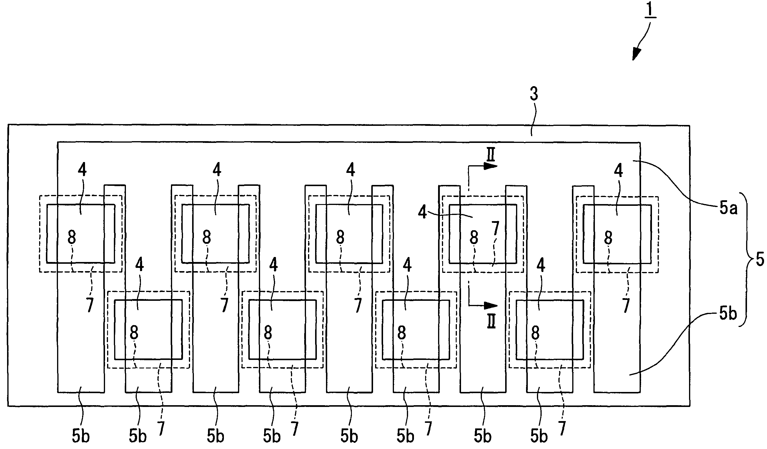
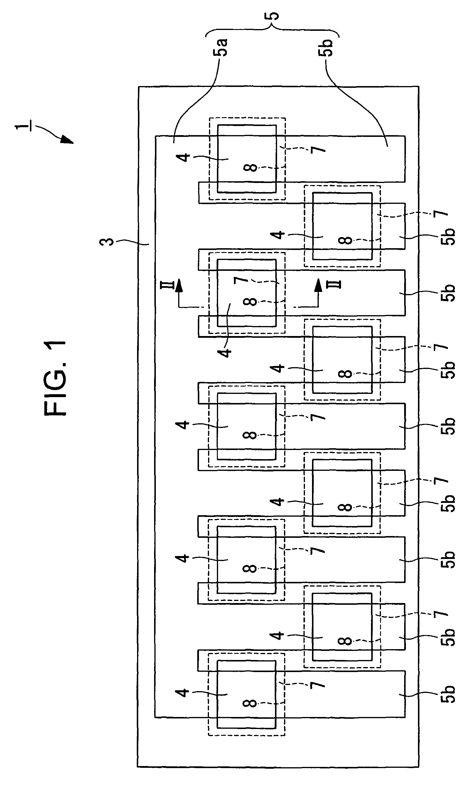
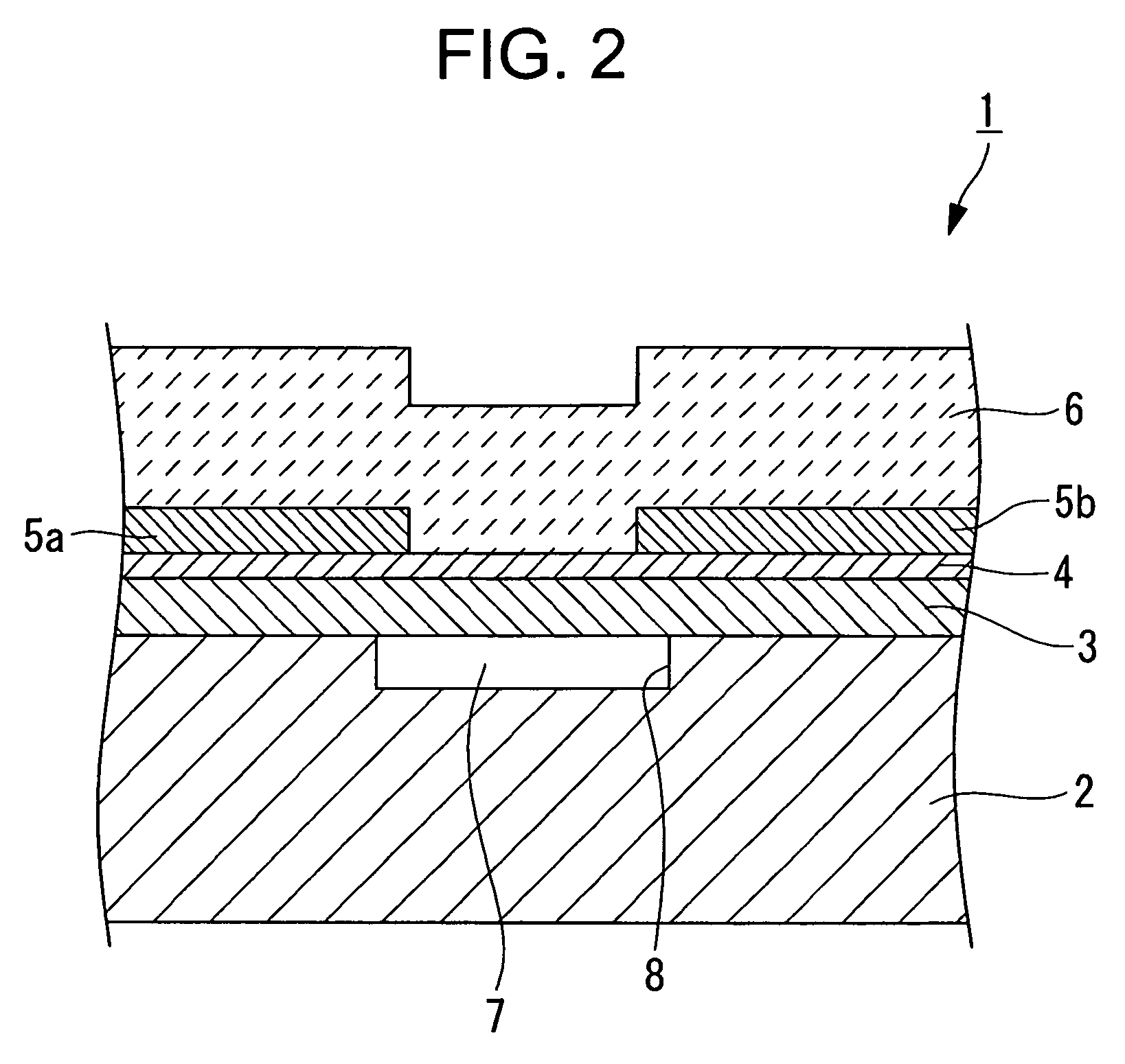
[0027]FIG. 1 is a plan view of a thermal head which is a heating resistance element component according to this embodiment, which shows a state where a protective film is removed. FIG. 2 is a sectional view taken along an arrow II-II of FIG. 1.

[0028]A heating resistance element component 1 according to this embodiment is, for example, a thermal head used in a thermal activation device 25 (see FIG. 4) using a thermosensitive adhesive label (hereinafter, referred to as “thermal head”).

[0029]As shown in FIG. 2, the thermal head 1 includes a supporting substrate (hereinafter, referred to as “substrate”) 2 and an undercoat (insulating film) 3 formed on the substrate 2. As shown in FIG. 1 and FIG. 2, a plurality of heating resistors 4 are formed (arranged) in a zigzag shape along a main scanning direction (horizontal direction in FIG. 1) on the unde...

second embodiment

[0052]A heating resistance element component according to the present invention is described with reference to FIG. 3. FIG. 3 is a plan view of a thermal head which is the heating resistance element component according to this embodiment.

[0053]A heating resistance element component 11 according to this embodiment is different from the thermal head 1 according to the first embodiment in that the width of the common wire 5a or the width of the individual wires 5b is smaller in an area adjacent to the heating portions of the heating resistors 4 along the main scanning direction than the width of the common wire 5a or the width of the individual wires 5b in an area located in the vicinity of the heating portions of the heating resistors 4. Other components are the same as those described above according to the first embodiment, and thus their descriptions are omitted here.

[0054]According to the heating resistance element component 11 according to this embodiment, the heating resistors 4...


PUM


Abstract

Provided is a heating resistance element component, including: a supporting substrate; an insulating film laminated on the supporting substrate; a plurality of heating resistors formed on the insulating film, the plurality of heating resistors being arranged in a zigzag shape along a main scanning direction and having a substantially square shape; a common wire connected to one end of each of the plurality of heating resistors; individual wires each connected to another end of the each of the plurality of heating resistors; and concave portions formed in regions which are opposed to the plurality of heating resistors and are located on a surface of the supporting substrate, in which an arrangement pitch of the plurality of heating resistors in a sub-scanning direction is larger than an arrangement pitch of the plurality of heating resistors in a main scanning direction.

Description

BACKGROUND OF THE INVENTION[0001]1. Field of the Invention[0002]The present invention relates to a heating resistance element component (thermal head) which is used in a thermal activation device, and selectively drives a plurality of heating elements based on thermal activation data to thermally activate a thermosensitive adhesive layer provided on a rear side of a sheet-like base.[0003]2. Description of the Related Art[0004]There is generally known a thermal activation device which performs recording and thermal activation to a thermal activation starchy sheet including a thermosensitive adhesive layer formed on a rear surface side of a recording surface of a sheet-like base. The thermosensitive adhesive layer is formed of, for example, a material which is not adhesive at about room temperature but expresses adhesion through thermal activation by being heated to about 50 to 150° C. In the thermal activation, a large area needs to be heated to obtain adhesion, which requires a cons...

Claims


Application Information

Patent Timeline
Patent Type & Authority Patents(United States)
IPC IPC(8): B41J2/335
CPCB41J2/3351B41J2/33515B41J2/3353B41J2/3355B41J2/33585
Inventor SHOJI, NORIYOSHIMOROOKA, TOSHIMITSUSANBONGI, NORIMITSUSATO, YOSHINORIKOROISHI, KEITARO
Owner SEIKO INSTR INC
Why Eureka
Try Eureka