Imaging device

a technology of imaging device and image, which is applied in the direction of picture signal generator, television system scanning details, television system, etc., can solve the problems of reducing the performance of the camera, affecting the safety, design and performance, and reducing the comfort of the user, so as to improve the color reproducibility. , the effect of free from discoloration

Inactive Publication Date: 2010-12-14
COLLABO INNOVATIONS INC
View PDF13 Cites 74 Cited by
  • Summary
  • Abstract
  • Description
  • Claims
  • Application Information

AI Technical Summary

Benefits of technology

[0014]An object of the present invention is providing an imaging device that causes no discoloring under high temperature or high irradiation and has high color reproducibility.
[0017]First and second blue filters different in peak wavelength from each other are used as blue filters selectively transmitting a wavelength band belonging to blue. This can compensate the property that the transmission band in the low wavelength region is narrow compared with filters made of organic materials, and thus can improve the color reproducibility.
[0018]As described above, according to the present invention, use under high temperature or high irradiation is permitted, and the color reproducibility is improved. Thus, an imaging device free from discoloring due to high temperature or high irradiation and having high color reproducibility can be provided.

Problems solved by technology

There are problems as follows in relation to the position at which a camera is mounted.
That is, (1) placement of a camera inside a car may cause disfigurement, degrade the comfort and narrow the vision of the driver, (2) placement of a camera in an engine compartment may cause a failure because the surrounding environment is very hostile, and (3) placement of a camera on the side of a door or on an engine compartment may adversely affect the safety, the design and the performance such as aerodynamic drag.
While the prior art technology described above permits a camera to be mounted at a position where no vehicle performance is degraded, it disadvantageously restricts the performance of a camera.
That is, the following problems arise: (1) the sensitivity of the camera deteriorates because the camera takes images of the outside through a half mirror; (2) the vision range allowed to be imaged is limited, despite of efforts made for the orientation and viewing angle of the camera, because the camera mounting position is inside a door mirror; and (3) while omission of door mirrors is now under examination, this technology is not ready for this omission.
However, as is well known, the temperature inside a vehicle, including inside its door mirror, parked under the hot sun in the midsummer becomes very high.
When a camera is mounted on the outer surface of the vehicle, a use environment problem of the camera being exposed to direct sunlight occurs.
In other words, in the prior art imaging device using pigment filters, discoloring (degradation in color separation characteristics) occurs due to high temperature or high irradiation.
For this reason, placement of a camera on the outer surface of a vehicle, inside a vehicle and inside an engine compartment causes a problem that the color reproducibility may deteriorate under the influence of the ambient temperature and direct sunlight.
However, filters made of inorganic materials have a problem that, in color separation in the red (R), green (G) and blue (B) wavelength bands, the transmission band is narrow in spectral characteristics on the low-wavelength side, compared with filters of organic materials.
This however causes another problem of worsening the S / N of color signals.

Method used


Image

  • Imaging device
  • Imaging device
  • Imaging device

Examples


Embodiment Construction

[0032]Hereinafter, preferred embodiments of the present invention will be described with reference to the accompanying drawings.

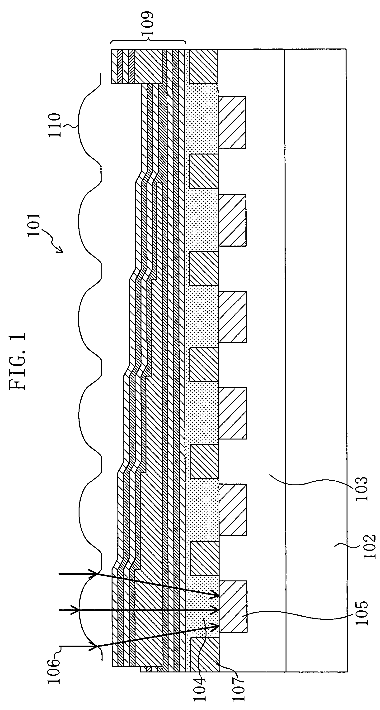
[0033]FIG. 1 is a cross-sectional view showing a structure of an image sensor of an imaging device of an embodiment according to the present invention. As shown in FIG. 1, in an image sensor 101, an n-type layer 102 and then a p-type layer 103 are formed in a silicon semiconductor substrate, and an interlayer insulating film 104 is formed on the p-type layer 103. Photodiodes (photoelectric conversion elements) 105 are formed in the p-type layer 103 by ion implantation of an n-type impurity. The photodiodes 105, which respectively correspond to unit pixels of the image sensor 101, photoelectrically convert incident light 106. The photodiodes 105 are isolated from one another with isolation regions 107.

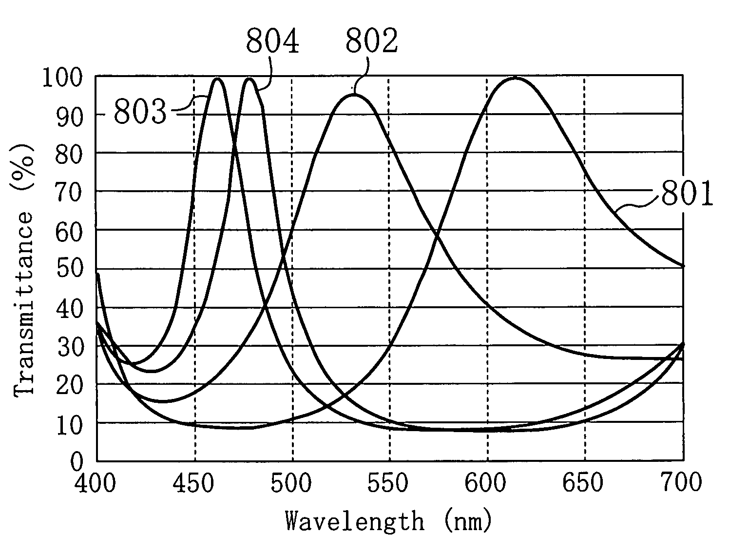
[0034]Multilayer filters 109 made of dielectrics are formed on a light-shading film (not shown) formed to suppress light from being incident on the isolation r...


PUM


Abstract

An imaging device free from discoloring under high temperature or high irradiation and having high color reproducibility is provided. Multilayer filters made of inorganic materials are provided above respective photoelectric conversion elements. The filters include red filters having predetermined spectra characteristics, green filters having predetermined spectral characteristics, and two kinds of blue filters having spectral characteristics different in peak wavelength.

Description

CROSS-REFERENCE TO RELATED APPLICATIONS[0001]This application claims priority under 35 U.S.C.§119 on Patent Application No. 2006-143313 filed in Japan on May 23, 2006, the entire contents of which are hereby incorporated by reference.BACKGROUND OF THE INVENTION[0002]1. Field of the Invention[0003]The present invention relates to an imaging device, and more particularly, to a technology of permitting an imaging device that requires high reliability and is often used under low color rendering illumination, such as a car-mounted imaging device, to provide good images.[0004]2. Description of Related Art[0005]In recent years, to enhance the safety of travel of vehicles, there have been proposed a number of systems of monitoring the surroundings of a vehicle with an imaging device mounted in the vehicle and systems using various types of information included in a monitored image.[0006]Examples of such systems include, for example: a system in which motion of a neighboring vehicle is detec...

Claims


Application Information

Patent Timeline
Patent Type & Authority Patents(United States)
IPC IPC(8): H04N3/14H04N9/083H04N5/335H04N9/04G02B5/20H01L27/14H04N9/07
CPCH01L27/14621H01L27/14632H01L27/14627
Inventor SHIMIZU, MINAKOFUJII, TOSHIYAINOKUMA, KAZUYUKI
Owner COLLABO INNOVATIONS INC
Why Eureka
Try Eureka