Metal halide reflector lamp

a reflector lamp and metal halide technology, applied in the field of metal halide reflector lamps, can solve the problems of forming a lifetime risk, light through the reflector neck being translucent, and deviations in color, and achieve the effects of no discoloration, good light absorption properties, and easy processing

Inactive Publication Date: 2012-10-11
KONINKLIJKE PHILIPS ELECTRONICS NV
View PDF2 Cites 1 Cited by
  • Summary
  • Abstract
  • Description
  • Claims
  • Application Information

AI Technical Summary

Benefits of technology

[0010]Besides being lighttight, the sleeve material has to be easy processable, heat-resistant up to the region of about 400° C. to about 500° C., cheap, shows no discoloring due to oxidation and has good light absorbing properties, that means a small reflection coefficient. For suitable materials the above points to metals or ceramics. Ceramics will probably be more expensive. In some embodiments of the invention described below a sleeve made from aluminum (Al) is used. It may be advantageous to provide the sleeve with a black coating.
[0011]It is advantageous to have a blackened inner surface of the sleeve for the prevention of the temperature rising too high inside the neck and the adjoining reflector-space. The thus formed black surface will absorb effectively infrared radiation and thus prevent reflection of IR back to the lamp. A further advantageous improvement is to have blackened also the outer surface of the sleeve, so as to improve the transfer of heat to the space outside the lamp.

Problems solved by technology

The heating of the leadthrough construction leads to deviations in the color and forms a lifetime risk.
However this leads to a further problem being the occurrence of spill light through the reflector neck being translucent which is annoying to an observer.

Method used


Image

  • Metal halide reflector lamp
  • Metal halide reflector lamp
  • Metal halide reflector lamp

Examples


Embodiment Construction

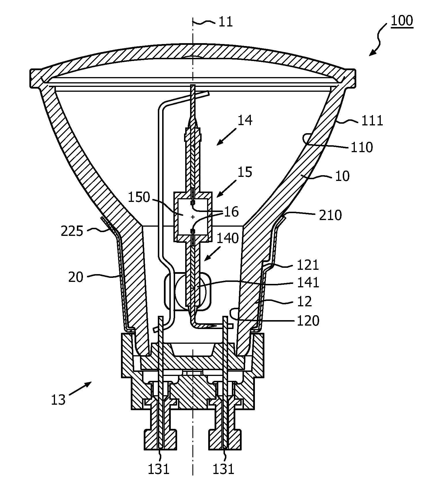
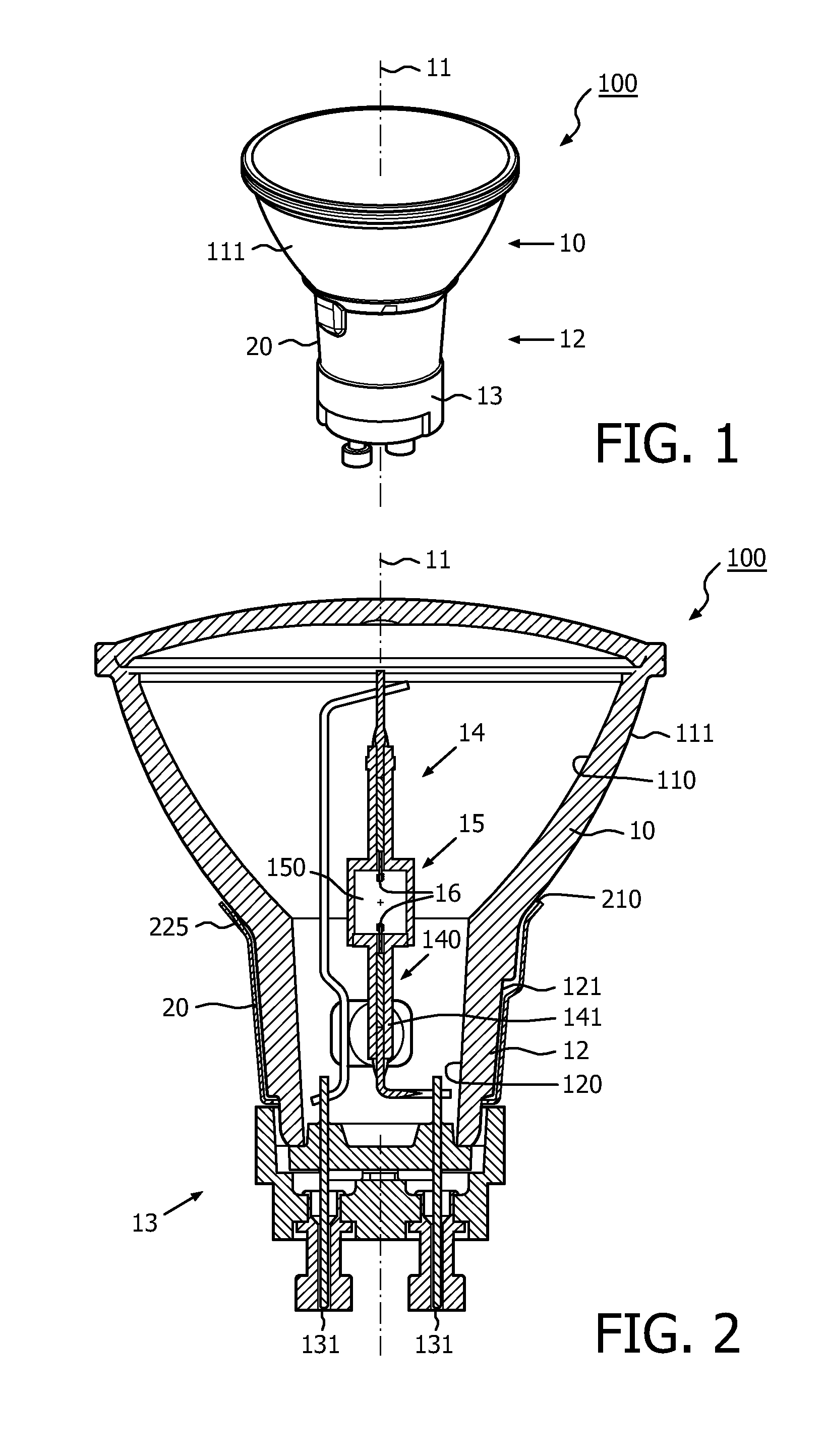
[0020]An embodiment of a lamp according to the invention is shown in FIG. 1 in side view and in FIG. 2 in cross-section, wherein a high pressure discharge lamp 100 comprises:

[0021]a concave(curved inward) reflector body 10 with an axis 11 and a hollow neck portion 12 around the axis having an inner 120 and an outer 121 wall surface, the neck portion being provided with a lamp cap 13 at its end pointing away from the reflector body; the reflector body having a reflective surface 110 on its inwardly curved side and an outer side 111 opposite the inwardly curved side; the inner wall surface of the hollow neck portion being substantially non-reflective;

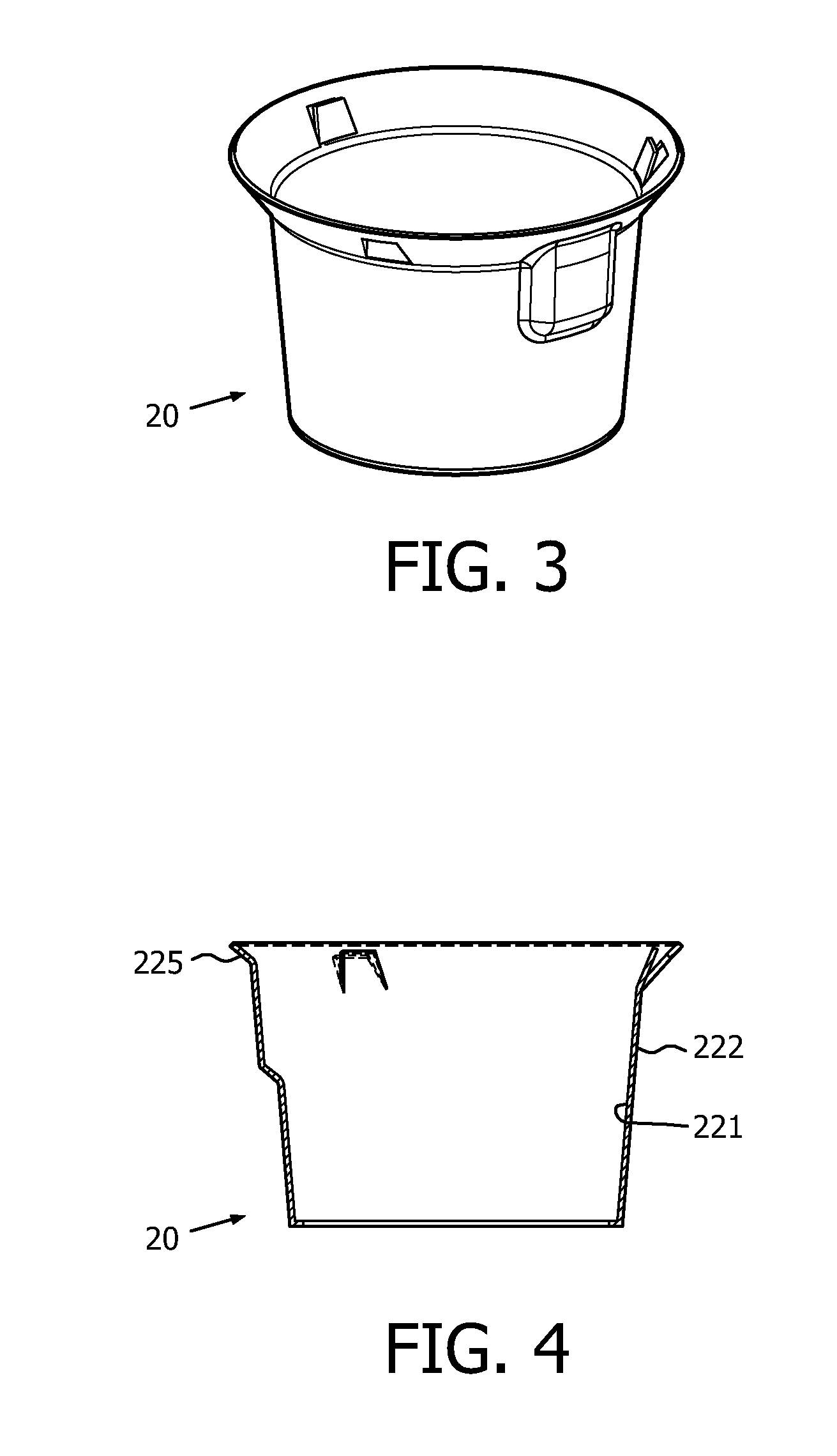
[0022]a discharge vessel 14 having at least one leadthrough construction 140 and wherein the at least one leadthrough construction is at least partly surrounded by the neck portion and in that the neck portion is surrounded by a sleeve 20 being opaque for light, that is being opaque for visible radiation.

[0023]The sleeve 20 is shown in de...


PUM


Abstract

The invention relates to a high pressure discharge lamp (100) comprising: a concave (curved inward) reflector body (10) with an axis (11) and a hollow neck portion (12) around the axis having an inner (120) and an outer (121) wall surface, the neck portion being provided with a lamp cap (13) at its end pointing away from the reflector body; the reflector body having a reflective surface (110) on its inwardly curved side and an outer side (111) opposite the inwardly curved side; the inner wall surface of the hollow neck portion being substantially non-reflective; a discharge vessel (14) having at least one leadthrough construction (140). According to the invention the at least one leadthrough construction is at least partly surrounded by the neck portion and in that the neck portion is surrounded by a sleeve (20) being opaque for light, that is being opaque for visible radiation.

Description

FIELD OF THE INVENTION[0001]The invention is related to a metal halide reflector lamp, in particular such a lamp of very compact size having a light source with a ceramic discharge vessel, also known as ceramic discharge tube or as ceramic burner. Metal halide lamps provided with a ceramic discharge vessel are commonly known, for instance as CDM lamps.BACKGROUND OF THE INVENTION[0002]In reflector lamps it is common that the reflector body has a neck shaped portion called neck, which end is provided with a lamp cap including electric contacts suitable to provide electrical connections with contact members of a lamp holder. Commonly the neck shaped portion of the reflector body is made of glass, glass ceramic, quartz glass, quartz or the like and is translucent.[0003]Discharge vessels for CDM lamps are provided with feedthrough constructions for electrically connecting internal electrodes with electric conductors extending from the electric contacts at the lamp cap. Each feedthrough c...

Claims


Application Information

Patent Timeline
Patent Type & Authority Applications(United States)
IPC IPC(8): H01J61/38F21Y101/00
CPCH01J61/025H01J61/523H01J61/34
Inventor VERHEES, PETRUS WILHELMUS CORNELIUS
Owner KONINKLIJKE PHILIPS ELECTRONICS NV
Why Eureka
Try Eureka