Electrically heatable fluid line

a technology of heat exchange fluid and heat exchange line, which is applied in the direction of fluid heaters, pipe heating/cooling, lighting and heating apparatus, etc., can solve the problems of complicated procedure, damaged heating conductor arrangement, and even complete separation of heating conductors, so as to simplify the manufacture of connections

Active Publication Date: 2010-12-14
NORMA GERMANY GMBH
View PDF8 Cites 9 Cited by
  • Summary
  • Abstract
  • Description
  • Claims
  • Application Information

AI Technical Summary

Benefits of technology

[0008]Therefore, it is the primary object of the present invention to make simpler the manufacture of a connection to the heating conductor arrangement.
[0010]As a result of the configuration according to the present invention, it is easily possible to sever the outer cross sectional area and to pull the outer cross sectional area from the end of the fluid line. The severing cut may actually be deeper than the thickness of the outer cross sectional area because the tool used for cutting does not contact the heating conductors of the heating conductor arrangement, but initially contacts the intermediate layer. After the outer cross sectional area has been cut, it can be easily pulled from the intermediate layer because the outer cross sectional area has a lower stability than the outer cross sectional area. It may be possible that the intermediate layer is partially destroyed which, however, is entirely acceptable. The intermediate layer can also be easily removed from the inner cross sectional area because it has a lower stability than the inner cross sectional area. As soon as the intermediate layer has been removed, the ends of the heating conductor arrangement are freely accessible. Under certain circumstances, the intermediate layer may already be removed when the outer cross sectional area is pulled off. In accordance with a preferred feature, the intermediate layer can be manually separated from the inner cross sectional area and the heating conductor arrangement. Consequently, the intermediate layer can be easily removed by a simple manipulation of a worker. No tools are required for removing the intermediate layer. It may be possible that the intermediate layer has already been removed when the outer cross sectional area is pulled off. In accordance with a preferred feature, the intermediate layer can be rubbed off. Accordingly, the worker can remove the intermediate layer by rubbing the intermediate layer with one or two fingers. This causes the intermediate layer to crumble, so that it can be removed from the inner cross sectional area and from the heating conductor arrangement. The materials used for the intermediate layer may be, for example, a material which is known from being used in electrical lines and which is known from electrical lines whose jacket of such an electrical line is severed form the insulation of the individual strands. Such a material used in the manufacture of electrical cables is also called a filling mixture or an “EPDM filling batch”. The material may contain, for example, EPDM, chalk, aluminum-hydroxide, paraffin waxes, and hydrocarbon waxes.
[0011]The intermediate layer is preferably electrically insulating. This makes it possible to use the intermediate layer as an electrical insulator in order to keep small the danger to the environment in the vicinity of the fluid line cause by the electrical current or voltage.
[0012]It is preferred in this connection that the heating conductor arrangement is in electrical contact with the intermediate layer. When the intermediate layer is electrically insulating, the heating conductor arrangement also requires only electrically insulating wires, then the heating conductor arrangement also only requires blank wires which makes the manufacture cheaper.
[0015]In accordance with a preferred feature, the material of the intermediate layer is selected from a group which includes silicon and rubber. An intermediate layer which is formed of one of these materials can be easily destroyed in the unlinked state and, thus, can be removed from the inner cross sectional area.
[0016]The inner cross sectional area is preferably constructed as a multiple layer area. This makes it possible in an easy manner to adapt the inner cross sectional area to the medium which is to be conducted through the duct.

Problems solved by technology

However, it is cumbersome and / or necessary to have a certain skill for being able to configure such a heatable fluid line in such a way it can be supplied with electrical power.
This is a very complicated procedure.
A great risk in doing that is the fact that when the outer cross sectional area is removed the heating conductor arrangement is also damaged or even entirely severed.

Method used


Image

  • Electrically heatable fluid line
  • Electrically heatable fluid line

Examples


Embodiment Construction

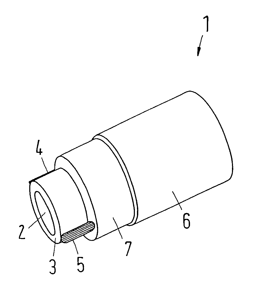
[0020]The drawing shows an electrically heatable fluid line 1 with a duct 2 through which a fluid can be conducted. The fluid is to be heated.

[0021]The duct 2 is surrounded by an inner cross sectional area 3 which can also simply be called the “inner layer”. The inner cross sectional area 3 may be constructed as a single layer or with multiple layers. The configuration of the inner cross sectional area 3 or the inner layer depends primarily on the medium which is to be conducted through the duct 2.

[0022]A heating conductor arrangement with two heating conductors 4, 5 is arranged at the circumference of the inner cross sectional area 3. In the illustrated embodiment, the heating conductors 4, 5 are aligned parallel to the axis of the duct 2. However, they can also be arranged helically around the inner cross sectional area 3. It is also possible to provide more than the two illustrated heating conductors 4, 5.

[0023]The heating conductors 4, 5 are constructed of a material which has a...


PUM


Abstract

An electrical heatable fluid line includes an inner cross sectional area which surrounds a medium conducting duct, a heating conductor arrangement which is arranged in a thermally conductive connection with the inner cross sectional area, and an outer cross sectional area which surrounds the heating conductor arrangement between the inner cross sectional area and the outer cross sectional area an intermediate layer which separates the heating conductor arrangement from the outer cross sectional area and which mechanically has a lower stability than the inner cross sectional area and the outer cross sectional area.

Description

BACKGROUND OF THE INVENTION[0001]1. Field of the Invention[0002]The present invention relates to an electrically heatable fluid line with an inner cross sectional area which surrounds a medium conducting duct, a heating conductor arrangement which is arranged in a thermally conductive connection with the inner cross sectional area, and an outer cross sectional area which surrounds the heating conductor arrangement.[0003]2. Description of the Related Art[0004]It is desirable in many cases to heat a fluid during its conveyance from a source to a user. Many types of these applications are conceivable. Only as an example, fluid lines should be mentioned which transport window washing liquid from a supply container to spray nozzles, or fluid lines used for transporting area in a motor vehicle having a diesel engine. Such electrically heatable fluid lines are known in the art. The inner cross sectional area must be constructed in such a way that it is resistant to the fluid conducted ther...

Claims


Application Information

Patent Timeline
Patent Type & Authority Patents(United States)
IPC IPC(8): F24H1/10F16L53/38
CPCF16L53/008F16L53/38F16L11/127F16L53/00
Inventor MULLER, DOMINIC
Owner NORMA GERMANY GMBH
Why Eureka
Try Eureka