
Arm retention system for physical therapy

a technology for retaining systems and arms, applied in handcuffs, medical science, building locks, etc., can solve the problems of reducing the effectiveness of the therapy program, reducing the likelihood of the user's hands and/or arms moving, and significant increase in recovery tim

Inactive Publication Date: 2010-12-21
MOSTAD MATT
View PDF24 Cites 7 Cited by
  • Summary
  • Abstract
  • Description
  • Claims
  • Application Information

AI Technical Summary

Benefits of technology

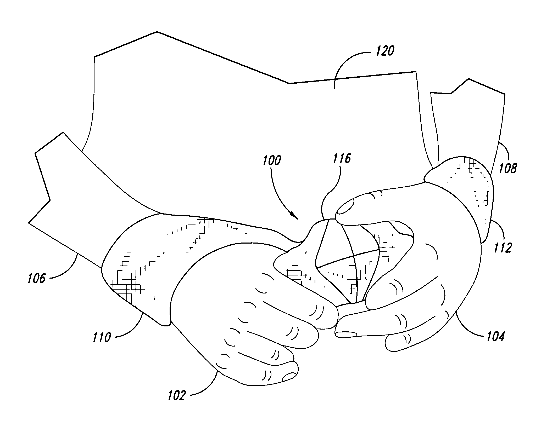
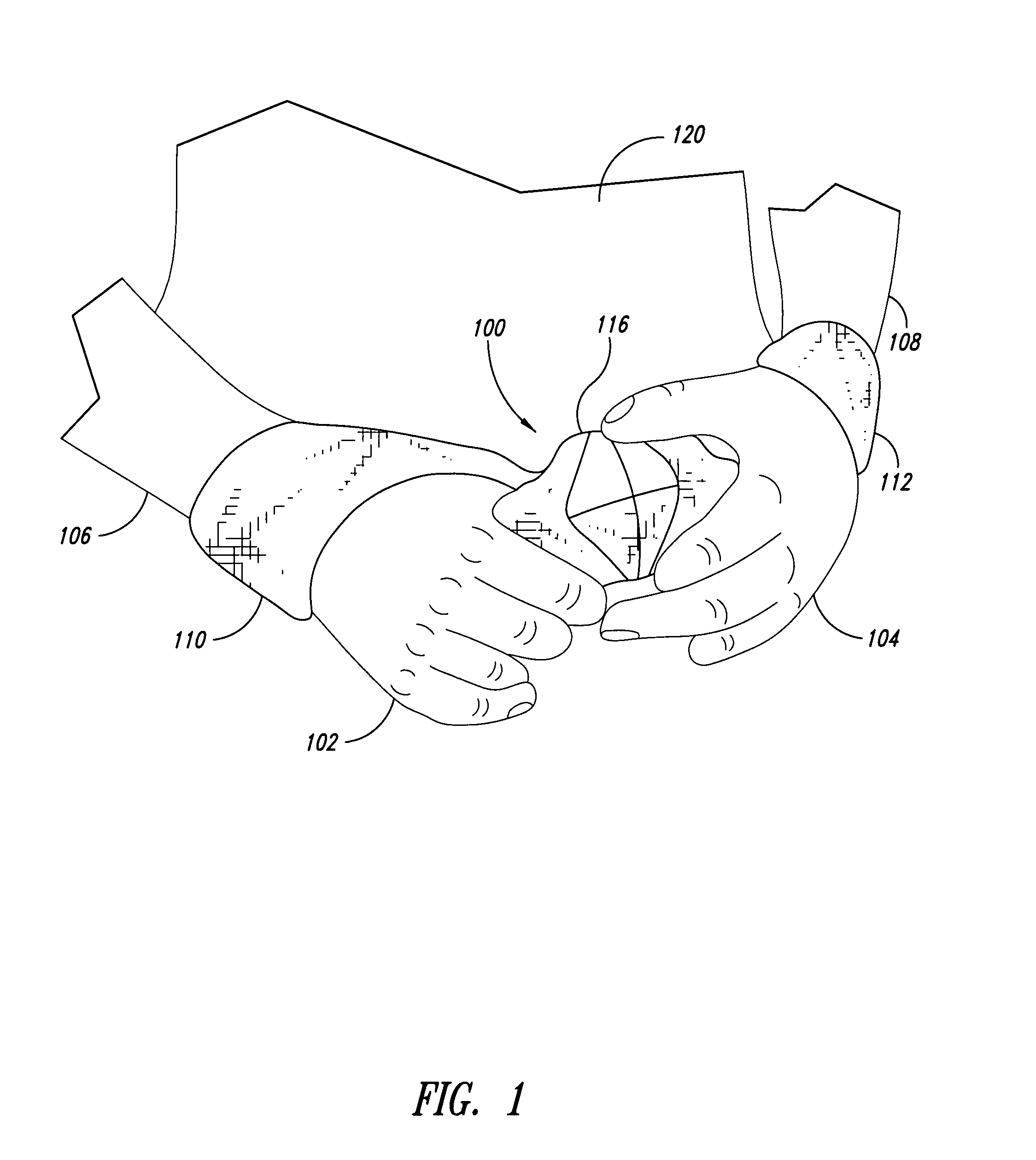
[0008]In some embodiments, a retention system is configured to receive both hands of an individual. Once the wear's wrists are positioned in the retention system, the wearer can manipulate the retention system until it comfortably holds the wearer's arms. In some embodiments, the wearer can conveniently manipulate (e.g., twist) the retention system in order to tighten the retention system and to loosen the retention system for removal.
[0009]When the user is located in a somewhat confined space, the retention system can help reduce the likelihood of the user's hands and / or arms moving outside of a desired space. Such retention systems can keep the user's arm in proximity to the user's body when, for example, performing a wide range of activities (e.g., sleeping, sitting, resting, and the like).
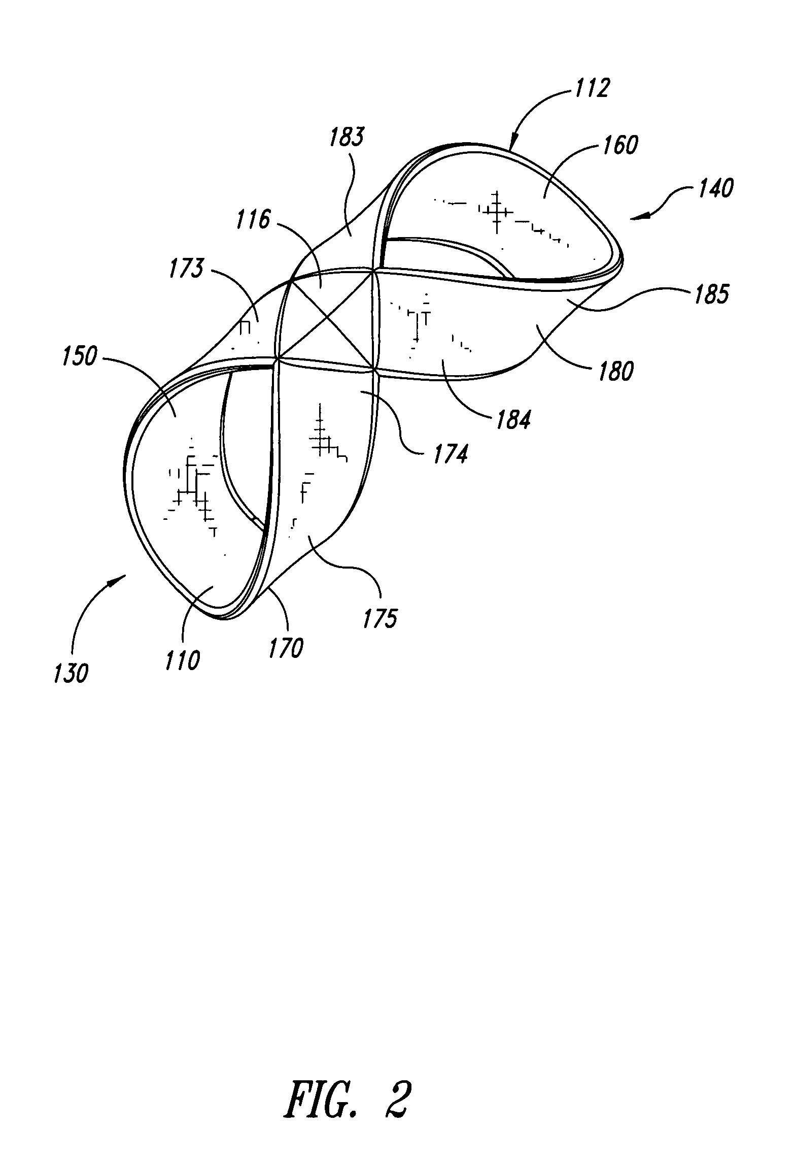
[0013]In some embodiments, a one-piece retention system is made of a continuous strip of fabric. Separate pieces of material can be coupled together to form the continuous strip. Retention systems made of fabric can effectively restrain without utilizing complicated moving mechanical components.
[0014]In some embodiments, a method for retaining a user's arm is provided. The method includes wearing a first compliant, drapable loop of a retention system on the user's right arm. The retention system includes a wide, flat strip of fabric folded upon itself to define the first compliant, drapable loop and a second compliant, drapable loop opposing the first loop. The second loop is worn on the user's left arm, such that a central section of the retention system is positioned between the right arm and the left arm. The central section connects the first loop to the second loop. In some embodiments, the effective lengths of the first and second loops are reduced to tighten the first and second loops about the right and left arms. This tightening can be performed while a first length of a strip defining the first loop and a second length of a strip defining the second loop remain generally constant. Accordingly, the retention system can be tightened or loosened even though the loops have a fixed length.

Problems solved by technology

Unfortunately, individuals often inadvertently move injured body parts outside the desired range of motion resulting in a significant increase in recovery time.
Conventional rigid and soft braces or slings for limiting body motion may be extremely uncomfortable, especially when worn for a long period of time, leading patients to refrain from wearing the braces for the prescribed lengths of time.
This may appreciably reduce the effectiveness of the therapy program.
Individuals, including injured and uninjured individuals, may have difficulty keeping their hands, arms, and other body parts away from other people or objects, especially when occupying a small or confined space.
Unwanted body movements may be disruptive and embarrassing and, consequently, highly undesirable.
For example, individuals traveling in transportation vehicles may want to limit their range of body movement because it may be difficult to keep their arms away from nearby passengers.
Unfortunately, armrests are unsuitable for limiting outward lateral arm movement, which may result in a violation of the personal space of the adjacent passenger and embarrassing situations.
Overweight or obese individuals may have more difficulty in keeping their hands and arms away from other passengers.

Method used


Image

  • Arm retention system for physical therapy
  • Arm retention system for physical therapy
  • Arm retention system for physical therapy

Examples


Embodiment Construction

[0033]The present detailed description is generally directed to retention systems configured to retain one or more body parts of a user. The body parts may be arms, hands, fingers, legs, ankles, feet, limbs, combinations thereof, and / or other anatomical features or appendages. Many specific details and certain representative embodiments are set forth in the following description and in FIGS. 1-15 to provide a thorough understanding of such embodiments. One skilled in the art, however, will understand that the disclosed embodiments may be practiced without one or more of the details described in the following description. As used herein, the term “arm” is broadly construed to include, without limitation, an upper limb of the human body. For example, the retention system may be applied to the limb extending from the shoulder to the hand. In various applications, retention systems can be worn about the wrists, forearms, or upper arms, even when performing different activities, includin...


PUM


Abstract

Retention systems, methods, and components for controlling body movement are shown and described. Retention systems can be used to reduce, limit, or substantially eliminate unwanted body movement, such as arm movement. The disclosed systems can be quickly and conveniently positioned on a user's arm to keep the arms against or near the torso of the wear. The retention system can be worn when performing normal everyday activities.

Description

CROSS-REFERENCES TO RELATED APPLICATIONS[0001]This application claims the benefit under 35 U.S.C. §119(e) of U.S. Provisional Patent Application No. 60 / 829,500 filed Oct. 13, 2006 and U.S. Provisional Patent Application No. 60 / 903,117 filed Feb. 23, 2007. These two provisional applications are incorporated herein by reference in their entireties.BACKGROUND[0002]1. Field[0003]The present disclosure and disclosed embodiments generally relate to retention systems, and more specifically, to arm retention systems.[0004]2. Description of the Related Art[0005]Physical therapy programs often involve restricting movement of an injured body part. It may be important to limit the range of motion of an injured body part to prevent aggravation of the injury and to increase the rate of healing. Unfortunately, individuals often inadvertently move injured body parts outside the desired range of motion resulting in a significant increase in recovery time. Conventional rigid and soft braces or slings...

Claims


Application Information

Patent Timeline
IPC IPC(8): A61B19/00E05B75/00
CPCE05B75/00Y10T70/404
Inventor MOSTAD, MATT
Owner MOSTAD MATT
Learn More