
Tapered braking device for electric winches

a braking device and electric winch technology, applied in the direction of winding mechanism, hoisting equipment, etc., can solve the problems of difficult maintenance, tapered face loss of braking efficacy, and tapered face loss, so as to simplify maintenance and reduce costs. , the effect of safe braking

Active Publication Date: 2010-12-28
XIE YUZHI +1
View PDF9 Cites 0 Cited by
  • Summary
  • Abstract
  • Description
  • Claims
  • Application Information

AI Technical Summary

Benefits of technology

[0005]An object of the present invention is to provide a tapered braking device for electric winches which has the advantages of larger braking area, good braking effects, lower replacement cost of parts and avoiding wearing a gear box directly.
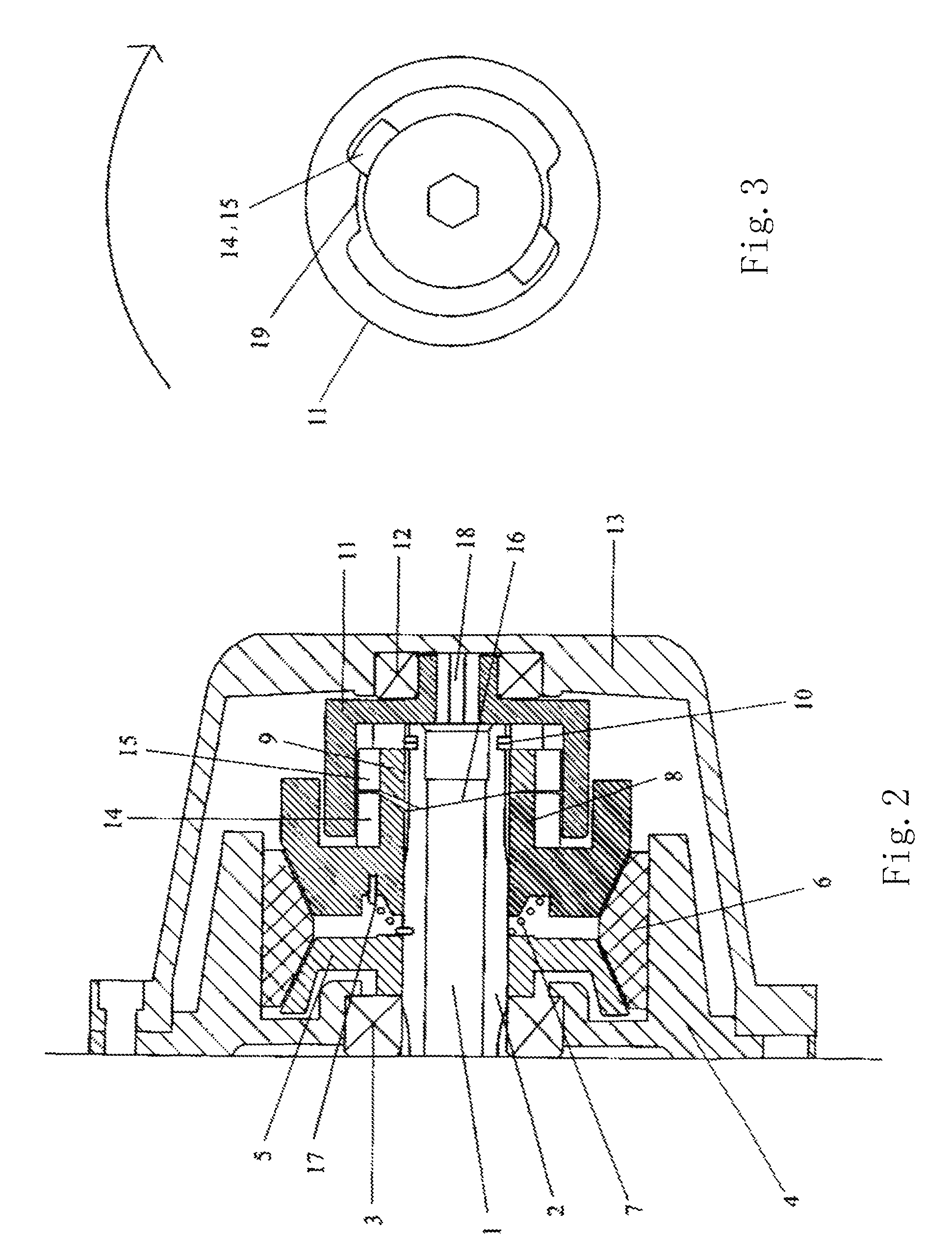
[0016]The optimal material selection for the wedge shape support and the wedge shape piece B can ensure that the friction wear faces concentrate in the braking plates and the braking area is doubled, so the braking force increases and the braking is safe. Additionally, when the braking wear is serious, it only needs to replace the braking plates made of friction materials, which can simplify maintenance and reduce the costs greatly.

Problems solved by technology

However, the braking device has the shortcomings that the braking area and the braking force produced by the single tapered face braking is small, which will easily cause slipping phenomena, and more chiefly the braking plate directly acts on the tapered face of the gear box, which will easily make the tapered face to be wearing directly, so that the tapered face lose braking efficacy.
Then the gear box must be replaced, which causes difficult maintenance and high replacement cost of parts.

Method used


Image

  • Tapered braking device for electric winches
  • Tapered braking device for electric winches
  • Tapered braking device for electric winches

Examples


Embodiment Construction

[0027]The following is the detailed description of the embodiment of the present invention in connection with the appended drawings.

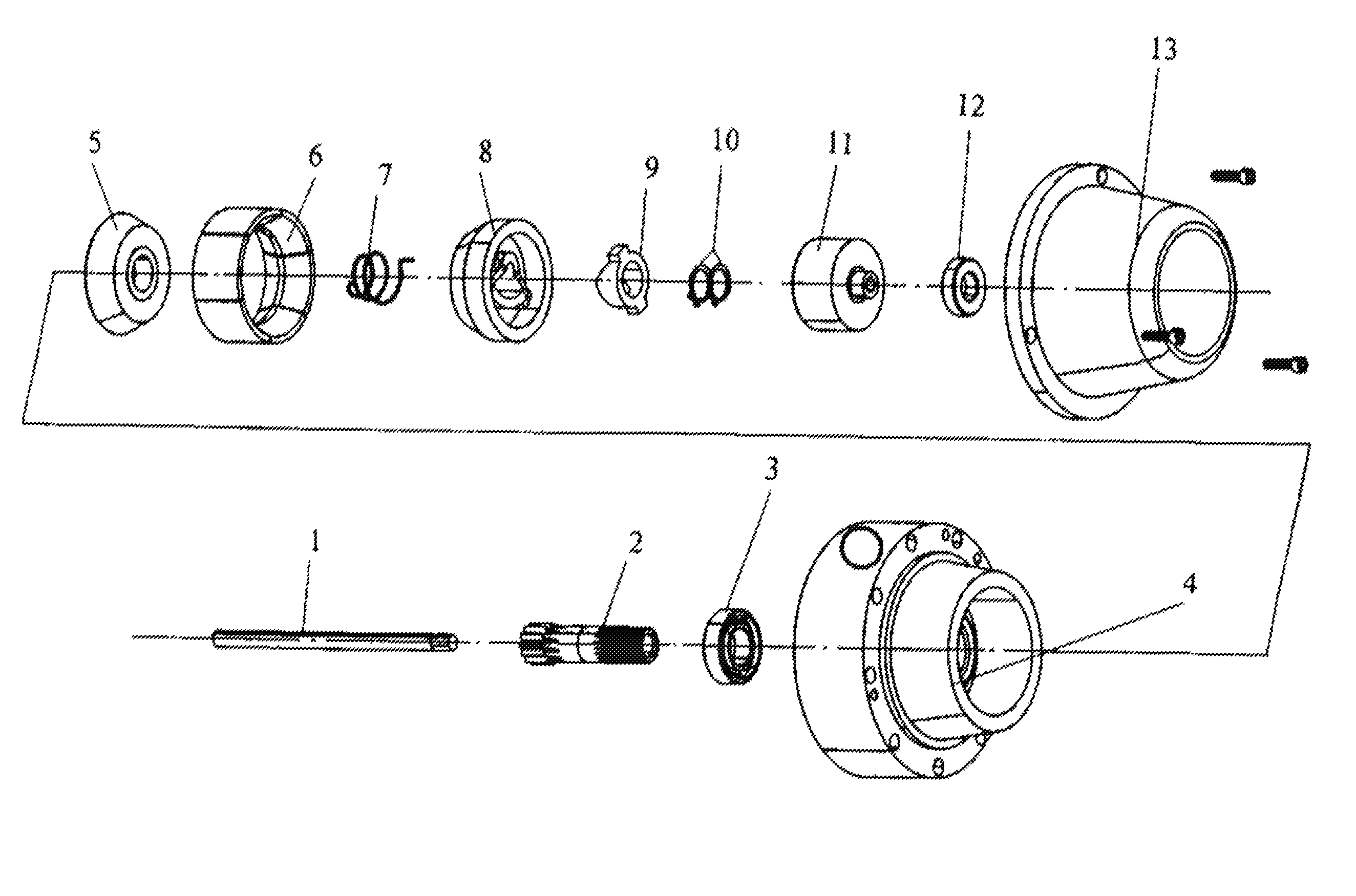
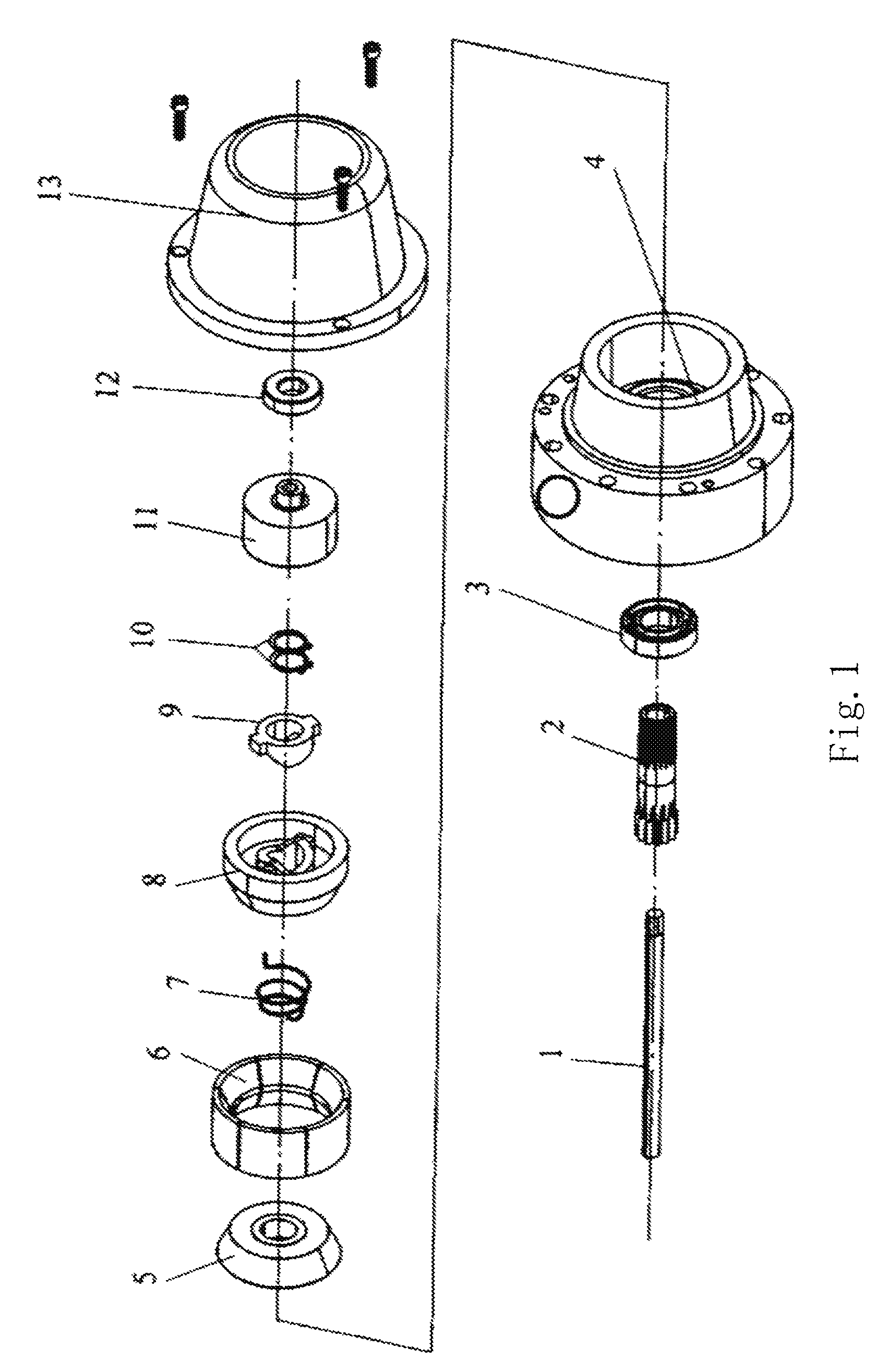
[0028]As shown in FIGS. 1-10, a tapered braking device for electric winches according to the present invention includes a gear box 4 fixed on an electric winch, a braking cover 13 fixedly connected with the gear box 4, and a section of hollow gear shaft 2 which extends into the center of the gear box 4 and is supported by a bearing 3. The hollow gear shaft 2 has a multikey structure. A section of core shaft 1 extending from a motor shaft passes through the hollow gear shaft 2, and one extended end portion of the core shaft 1 which extends out of the hollow gear shaft 2 is a hexahedron 18. Besides the bearing 3, a wedge shape support 5, an elastic element 7, a wedge shape piece B 8 and a wedge shape piece A 9 respectively sets on the section of gear shaft 2 from left to right.

[0029]Outer surfaces of the wedge shape support 5 and the wedge shape piece B 8...


PUM


Abstract

The present invention discloses a tapered braking device for electric winches which disposes a section of gear shaft, a section of core shaft, a wedge shape support, braking plates, an elastic element, a wedge shape piece A, a wedge shape piece B, a braking clutch base and so on in a gear box of an electric winch. When a motor works, the section of core shaft of the motor can drive the braking clutch base and the wedge shape pieces A, B to rotate, until a gap is formed between the friction faces of the wedge shape support and the wedge shape piece B and the braking plates so that the braking action stops. When the motor suddenly stops, a heavy load lifted by a tight wire rope reel provides a reverse pulling force so that the wedge shape piece B produces a reverse thrust force to push the friction faces of the braking plates, so the braking effect is achieved quickly. Based on the braking plates with the double tapered faces, the present invention can increase the braking area and the braking force and achieve safe braking. Furthermore, worn parts concentrate in the braking plates, so it only needs to replace the braking plates made of friction materials, which can simplify maintenance, reduce the costs and ensure service life of the gear box.

Description

CROSS-REFERENCE TO RELATED APPLICATIONS[0001]This application is a National Stage of International Application No. PCT / CN2007 / 002421, filed Aug. 13, 2007. This application claims the benefit and priority of Chinese Application No. 200610052983.9, filed Aug. 17, 2006. The entire disclosure of each of the above applications is incorporated herein by reference.FIELD OF THE INVENTION[0002]The present invention relates to a braking device, and more particularly to a tapered braking device for electric winches.DESCRIPTION OF THE PRIOR ART[0003]Electric brakes pull goods via reeling tight wire rope for self-aid and buddy aid in automobile accidents in the fields. For avoiding stall of tight wire rope caused by sudden power cut during retracting, braking devices are disposed for ensuring safe operation. Chinese Patent No. 01229143.9 discloses a braking device for power winches which includes a gear box, a braking cover, a section of gear shaft, a section of core shaft extending from a motor...

Claims


Application Information

Patent Timeline
Patent Type & Authority Patents(United States)
IPC IPC(8): B66D1/14
CPCB66D1/22B66D5/12
Inventor XIE, YUZHITSAO, KUO-HSIANG
Owner XIE YUZHI
Learn More