Golf swing-diagnosing system

a golf swing and diagnostic system technology, applied in the field of golf swing diagnostic system, can solve the problems of difficult for the golfer to find defects in her/his swing form and points to be corrected, and the golfer cannot provide the motion of the joints, etc., to achieve the effect of reducing the computation cost and the erroneous recognition ratio of attention-focused points, efficient diagnosis, and high accuracy

Inactive Publication Date: 2010-12-28
SUMITOMO RUBBER IND LTD
View PDF54 Cites 74 Cited by
  • Summary
  • Abstract
  • Description
  • Claims
  • Application Information

AI Technical Summary

Benefits of technology

[0010]The present invention has been made in view of the above-described problems. Therefore it is an object of the present invention to provide a convenient golf swing-diagnosing system capable of reducing a computing time period and an erroneous recognition ratio of attention-focused points, diagnosing a swing form, and providing advice for results of a diagnosis.

Problems solved by technology

However, these apparatuses are incapable of providing information useful for improving the golfer's swing form.
However, even though the frame corresponding to the specific moving point during the swing motion is extracted, the golfer cannot be provided with the motion of the joints and the like during the swing by merely looking at the extracted image.
Therefore it is difficult for the golfer to find defects in her / his swing form and points to be corrected.
Therefore the amount of computation is very large, and an erroneous recognition of the coordinates of the positions of the moving points occurs at a high percentage.
In this case, a camera is incapable of recognizing the moving points.
Consequently it is impossible to obtain the coordinates of the positions of the moving points.
Thus there is a high probability that the swing form is erroneously diagnosed.
Another problem of this motion-diagnosing apparatus is that although numerical data such as the angle of the arm and the angle of the golf club is computed from coordinate data obtained by pursuing the moving points P1 to P6, how to utilize the obtained numerical data is not apparent.
Because the above-described apparatuses are installed at golf shops or the like, users cannot check their swing form for a long time.
As such, these apparatuses are not convenient for the users.

Method used


Image

  • Golf swing-diagnosing system
  • Golf swing-diagnosing system
  • Golf swing-diagnosing system

Examples


examples

[0426]Table 6 shows results of a test conducted for 10 testers by using the golf swing-diagnosing system.

[0427]For each tester, the data of the behavior of a ball B including the deviation angle of the ball B, the sidespin amount, the deviation distance of the drop point of the hit ball B to the right or the left with respect to the straight direction, the trajectory height, the ratio of the ball speed to the head speed was obtained. The trajectory pattern was decided from the sidespin amount and the deviation angle. The results of the diagnoses made on the diagnosis items prepared for the decided trajectory pattern and the advice drill for overcoming defects were displayed for the testers.

[0428]

TABLE 6DeviationDeviationto leftTrajectoryBall speed / angleSidespinor rightheightheadTester(degree)(rpm)(yard)(yard)speedTrajectoryDiagnosis and adviceA4.5 to 459 to23.5 to201.34pullThe trajectory pattern of a ball you hit is pullleftleftlefthookhook. The swing orbit pattern of the club isout...


PUM


Abstract

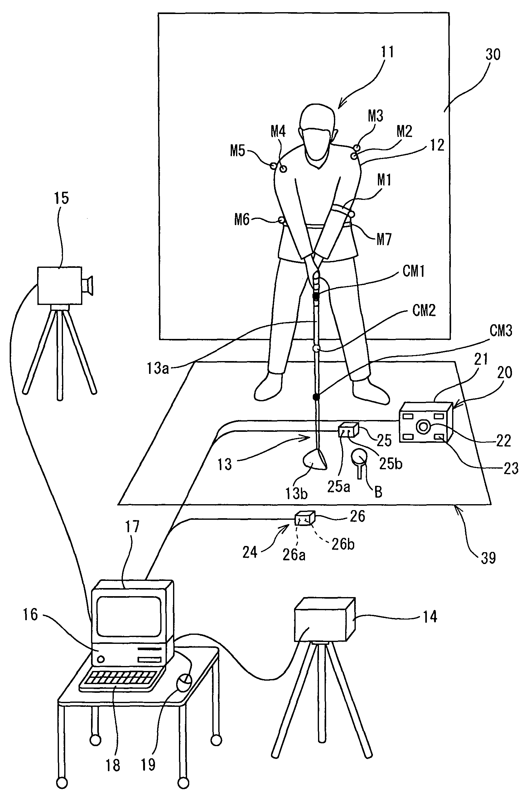
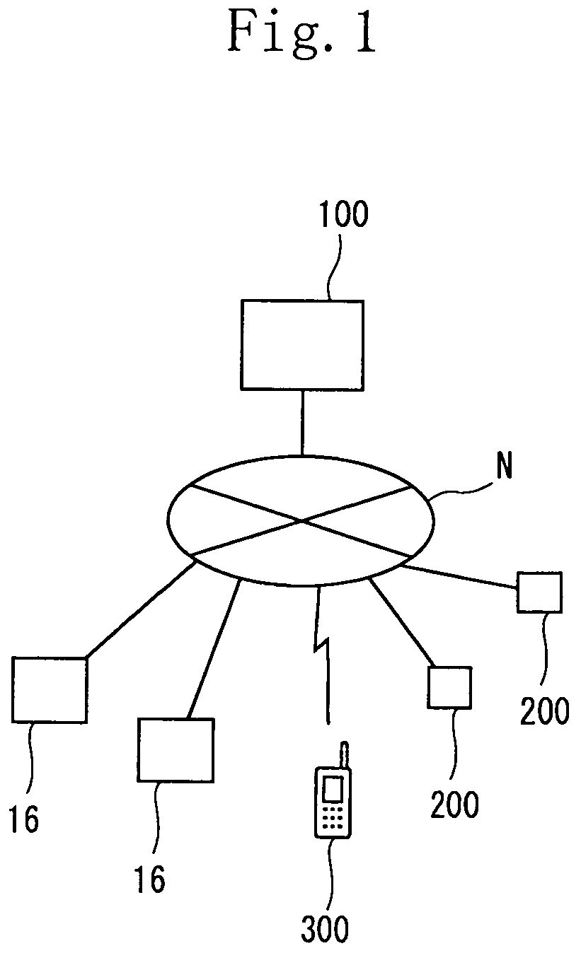
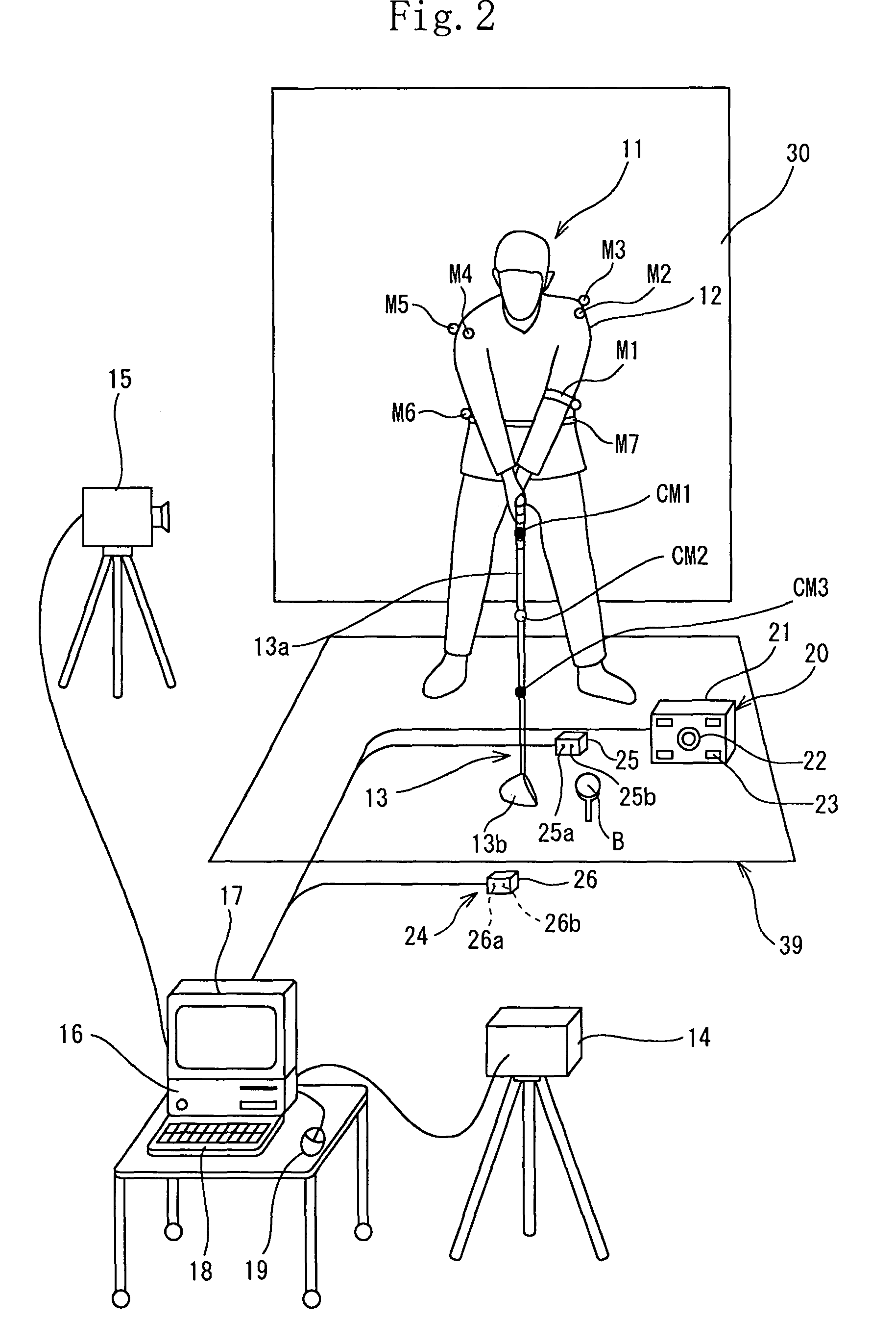
A computer (16) for capturing a colored moving image photographed by photographing means (14, 15) has an extraction means for extracting images having necessary swing postures as check-point images from a large number of still images constituting the color moving image; a means for obtaining a coordinate of a position of each of attention-focused points, which operate, in each of the check-point images, while a golfer (11) is swinging; a means for diagnosing a golfer's swing form by setting a plurality of diagnosis items for each trajectory pattern obtained by a ball motion measuring apparatus (20) to classify behavior of a golf ball and by comparing numerical data generated from data of the coordinate of the position of each of the attention-focused points with a judgement value set in each of a plurality of diagnosis items; and a means for outputting an advice drill corresponding to a result of a diagnosis.

Description

[0001]This nonprovisional application claims priority under 35 U.S.C. §119(a) on Patent Application No(s). 2004-091071 filed in Japan on Mar. 26, 2004 and 2004-091216 filed in Japan on Mar. 26, 2004, the entire contents of which are hereby incorporated by reference.FIELD OF THE INVENTION[0002]The present invention relates to a golf swing-diagnosing system and more particularly to a system of automatically and accurately diagnosing a golfer's swing form.BACKGROUND ART[0003]There are proposed various kinds of apparatuses for photographing a golfer's swing, automatically computing information such as a flight distance (distance from hitting point to drop point), trajectory, and the like of a hit golf ball by a computer, and displaying obtained information for a golfer. These apparatuses allow the golfer to examine the flight distance, trajectory, and the like of the hit ball. However, these apparatuses are incapable of providing information useful for improving the golfer's swing form....

Claims


Application Information

Patent Timeline
Patent Type & Authority Patents(United States)
IPC IPC(8): A63F9/24G06F17/00A63F13/00G06F19/00A63B69/00A63B69/36G06F17/40
CPCA63B24/0003A63B24/0021A63B69/3614A63B69/3658A63B2024/0012A63B2024/0031A63B2071/0647A63B2220/05A63B2220/35A63B2220/807A63B69/36A63B69/3623
Inventor UEDA, MASAHIKOONUKI, MASAHIDE
Owner SUMITOMO RUBBER IND LTD
Why Eureka
Try Eureka