

Perpendicular magnetic recording head having a main magnetic pole layer with a trapezoidally shaped flared part with a ratio of the length of the long base to that of the short base is equal to 1
a technology of magnetic recording head and main magnetic pole layer, which is applied in the field of perpendicular magnetic recording head, can solve the problems of increasing the recording density and reducing the leakage magnetic field from the flared part of the main magnetic layer, and achieves the prevention of side fringing, reducing the leakage magnetic field, and increasing the recording density
- Summary
- Abstract
- Description
- Claims
- Application Information
AI Technical Summary
Benefits of technology
Problems solved by technology
Method used
Image

Examples
Embodiment Construction
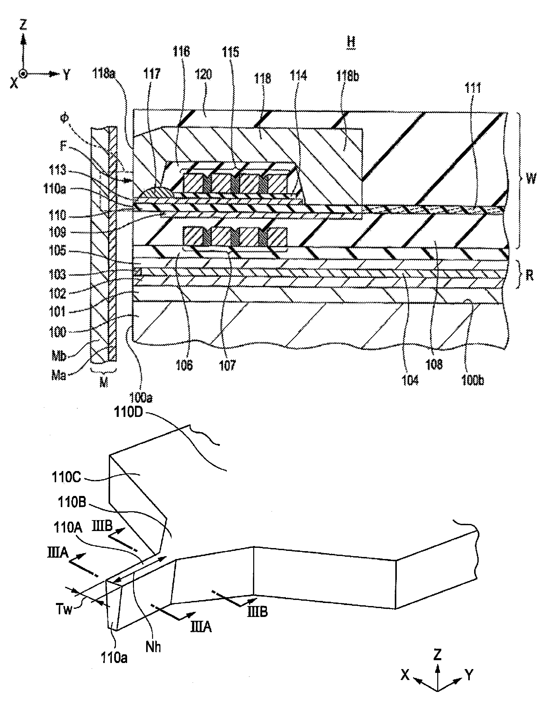
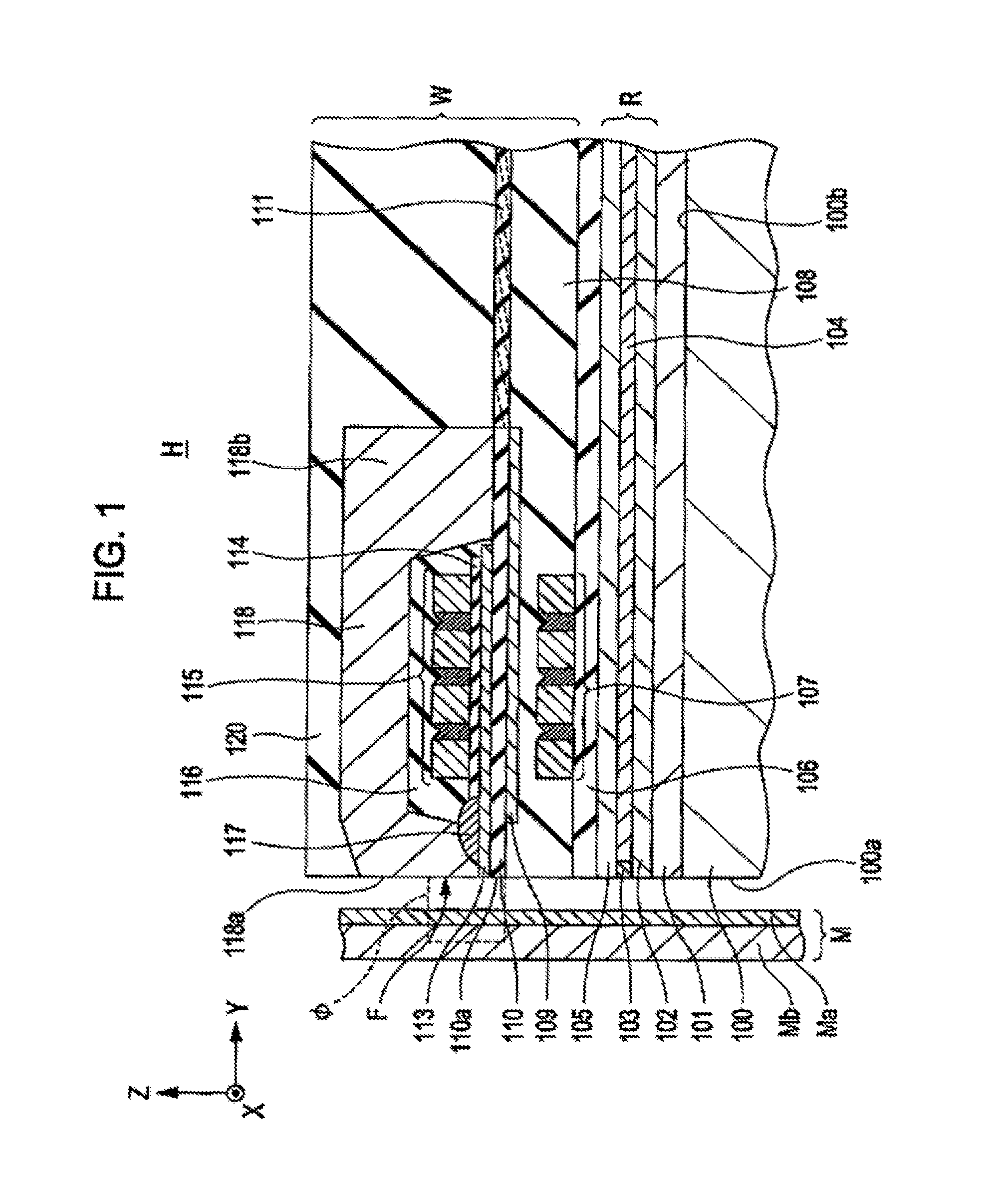
[0037]The present disclosure will now be described with reference to drawings, covering various non-exhaustive embodiments. In each of the drawings, the X direction is the track-width direction, the Y direction is the height direction, and the Z direction is the lamination direction in which the layers constituting a perpendicular magnetic recording head H are laminated, or the moving direction of a recording medium M.
[0038]FIG. 1 is a cross-sectional view showing a part of a laminated structure of a perpendicular magnetic recording head H according to one embodiment of the present disclosure as viewed in the track width direction. The perpendicular magnetic recording head H includes a read section R constituted from thin films laminated on a trailing side-end surface 100b of a slider 100, and a write section W. Writing is conducted by applying a perpendicular magnetic field Φ to the recording medium M to thereby magnetize a hard film Ma of the recording medium M in the perpendicula...
PUM
| Property | Measurement | Unit |
|---|---|---|
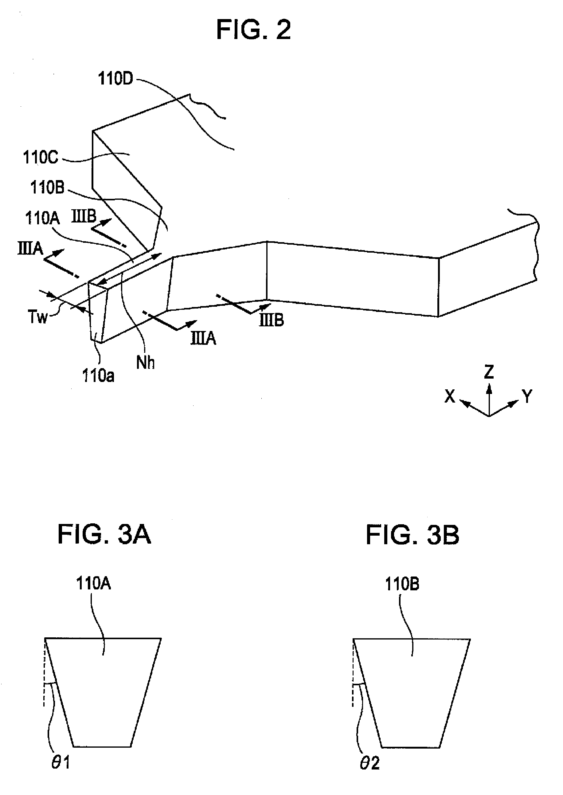
| angle | aaaaa | aaaaa |
| beveled angle θ2 | aaaaa | aaaaa |
| beveled angle | aaaaa | aaaaa |
Abstract
Description
Claims
Application Information