
Perpendicular magnetic recording head having flared part

a magnetic recording head and perpendicular magnetic technology, applied in the field of perpendicular magnetic recording head, can solve the problems of increasing the recording density and reducing the magnetic field from the flared part of the main magnetic layer, and achieve the effects of reducing the magnetic field, preventing the occurrence of side fringing, and increasing the recording density

Active Publication Date: 2007-10-11
TDK CORPARATION
View PDF3 Cites 16 Cited by
  • Summary
  • Abstract
  • Description
  • Claims
  • Application Information

AI Technical Summary

Benefits of technology

[0008]The present disclosure is made to overcome at least the existing problems described above. An object of the present disclosure is to provide a perpendicular magnetic recording head which can inhibit the increase in side fringe width and achieved higher recording density.
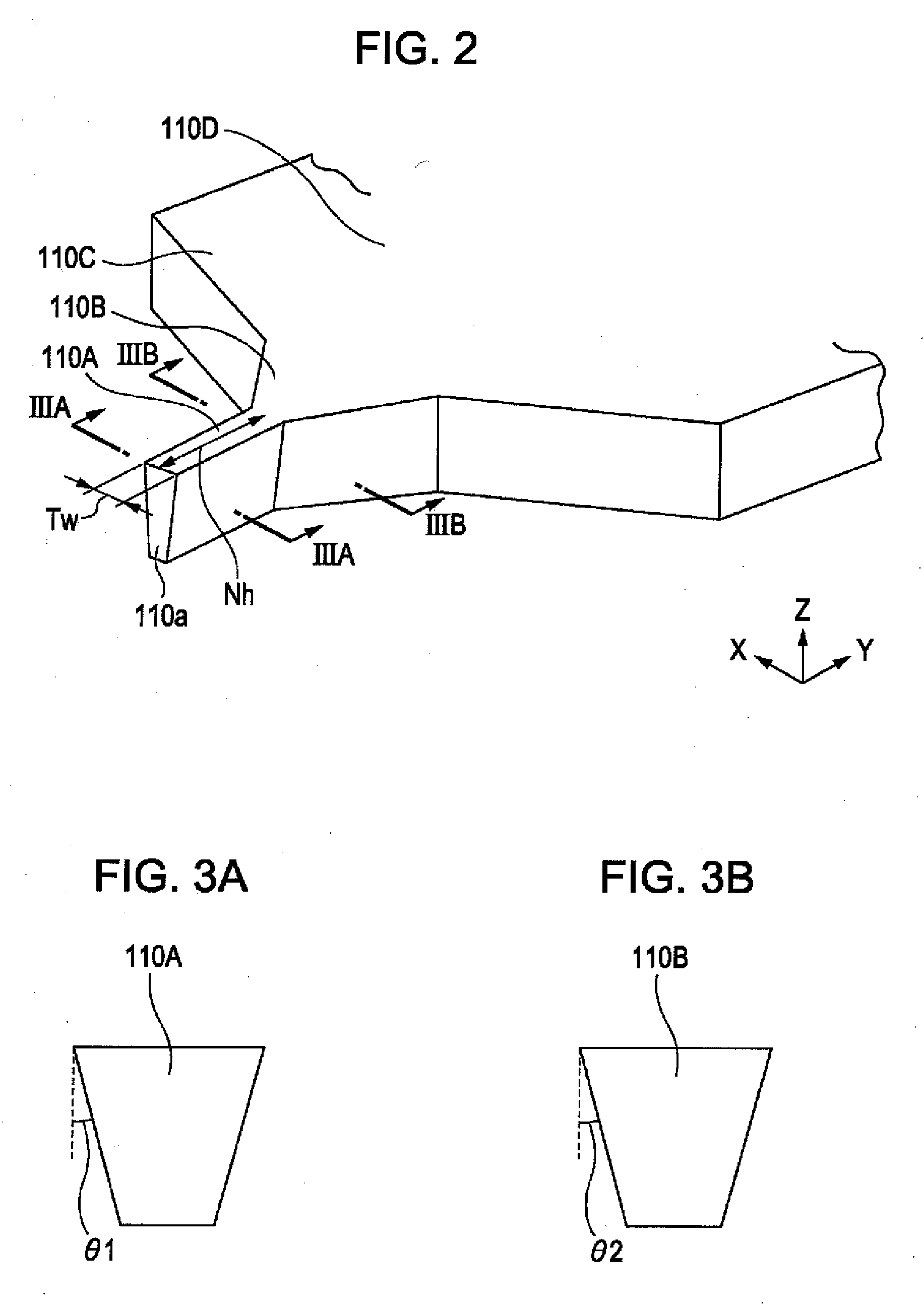
[0013]According to the present disclosure, a leakage magnetic field from the flared part of the main magnetic layer can be reduced by beveling. Thus, occurrence of side fringing can be prevented, and a perpendicular magnetic recording head that can attain higher recording density can be provided.

Problems solved by technology

The increase in side fringe width may lead to deletion of information magnetically recorded on a track adjacent to the track on which the recording is currently carried out, which is a problem.
In the related art, the intensity of the recording magnetic field is controlled not to exceed a certain level to keep, the side fringe width small, but this is disadvantageous for increasing the recording density.

Method used


Image

  • Perpendicular magnetic recording head having flared part
  • Perpendicular magnetic recording head having flared part
  • Perpendicular magnetic recording head having flared part

Examples


Embodiment Construction

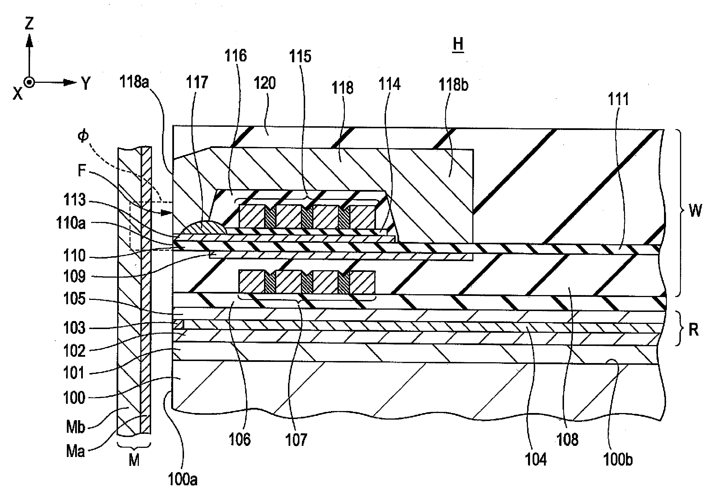
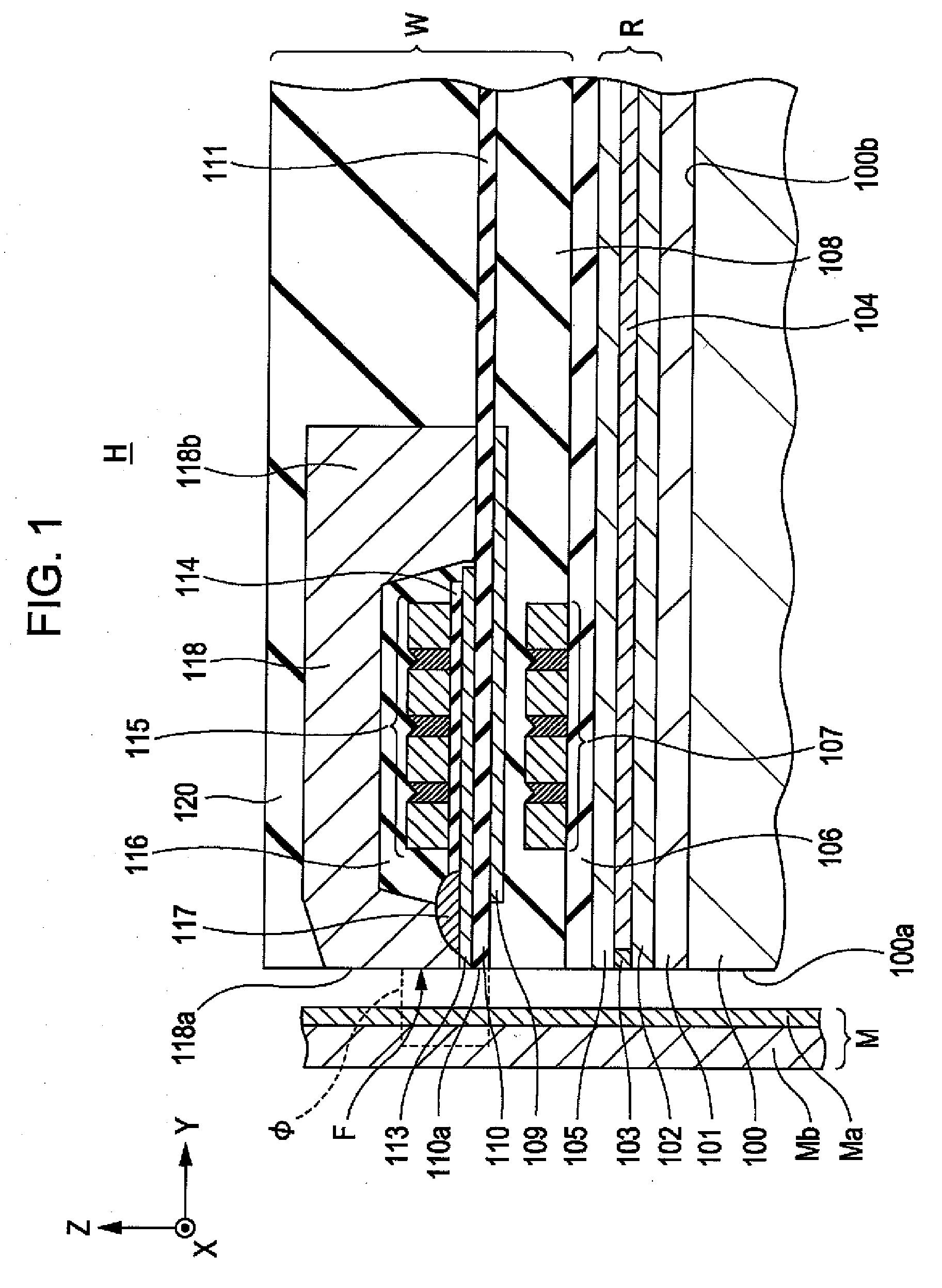
[0037]The present disclosure will now be described with reference to drawings, covering various non-exhaustive embodiments. In each of the drawings, the X direction is the track-width direction, the Y direction is the height direction, and the Z direction is the lamination direction in which the layers constituting a perpendicular magnetic recording head H are laminated, or the moving direction of a recording medium M.

[0038]FIG. 1 is a cross-sectional view showing a part of a laminated structure of a perpendicular magnetic recording head H according to one embodiment of the present disclosure as viewed in the track width direction. The perpendicular magnetic recording head H includes a read section R constituted from thin films laminated on a trailing side-end surface 100b of a slider 100, and a write section W. Writing is conducted by applying a perpendicular magnetic field Φ to the recording medium M to thereby magnetize a hard film Ma of the recording medium M in the perpendicula...


PUM

PropertyMeasurementUnit
angleaaaaaaaaaa
beveled angle θ2aaaaaaaaaa
beveled angleaaaaaaaaaa

Abstract

A perpendicular magnetic recording head includes a nonmagnetic insulating layer and a main magnetic pole layer disposed on the nonmagnetic insulating layer. The main magnetic pole layer includes a pole straight part exposed in an opposing surface opposite a recording medium and a flared part that extends from the pole straight part in a height direction. The flared part broadens in a track width direction as the flared part extends in the height direction. The pole straight part of the main magnetic pole layer as viewed from the opposing surface has a trapezoidal shape over its entire length, the trapezoidal shape being narrowed at the nonmagnetic insulating layer-side. The flared part as viewed from the opposing surface has a trapezoidal shape at least at a junction with the pole straight part, the trapezoidal shape being narrowed at the nonmagnetic insulating layer-side.

Description

RELATED APPLICATIONS[0001]This application claims the benefit of priority under 35 U.S.C. §119 to Japanese Patent Application No. 2006-106558 filed on Apr. 7, 2006, which is hereby incorporated by reference in its entirety.BACKGROUND[0002]1. Technical Field[0003]The present disclosure relates to a perpendicular magnetic recording head that records information by applying a perpendicular magnetic field to a recording medium.[0004]2. Description of the Related Art[0005]As is widely known, a perpendicular magnetic recording head has a main magnetic pole layer, a return path layer (auxiliary magnetic pole layer), and a coil layer that provides a recording magnetic field to the main magnetic pole layer and the return path layer. The main magnetic pole layer and the return path layer are laminated with a nonmagnetic layer therebetween and form a surface that opposes a recording medium (hereinafter this surface is referred to as “recording medium-opposing surface”). The area of the main ma...

Claims


Application Information

Patent Timeline
Patent Type & Authority Applications(United States)
IPC IPC(8): G11B5/147
CPCG11B5/1278G11B5/3116G11B5/1871
Inventor TOMA, YUSUKEKAMEDA, HIROSHIOZAKI, EIJI
Owner TDK CORPARATION
Learn More