Voltage clamps for energy snubbing

a technology of energy snubbing and voltage clamping, which is applied in the direction of dc-dc conversion, power electronics conversion efficiency, and emergency protective circuit arrangemen

Inactive Publication Date: 2010-12-28
LOCKHEED MARTIN CORP
View PDF31 Cites 25 Cited by
  • Summary
  • Abstract
  • Description
  • Claims
  • Application Information

AI Technical Summary

Problems solved by technology

A filter is coupled to the full-wave rectifier for producing output direct voltage for application to a load, whereby resonances between the output rectifier diode capacitances and transformer leakage inductance may generate voltage surges which may undesirably result in energy loss.

Method used


Image

  • Voltage clamps for energy snubbing
  • Voltage clamps for energy snubbing
  • Voltage clamps for energy snubbing

Examples


Embodiment Construction

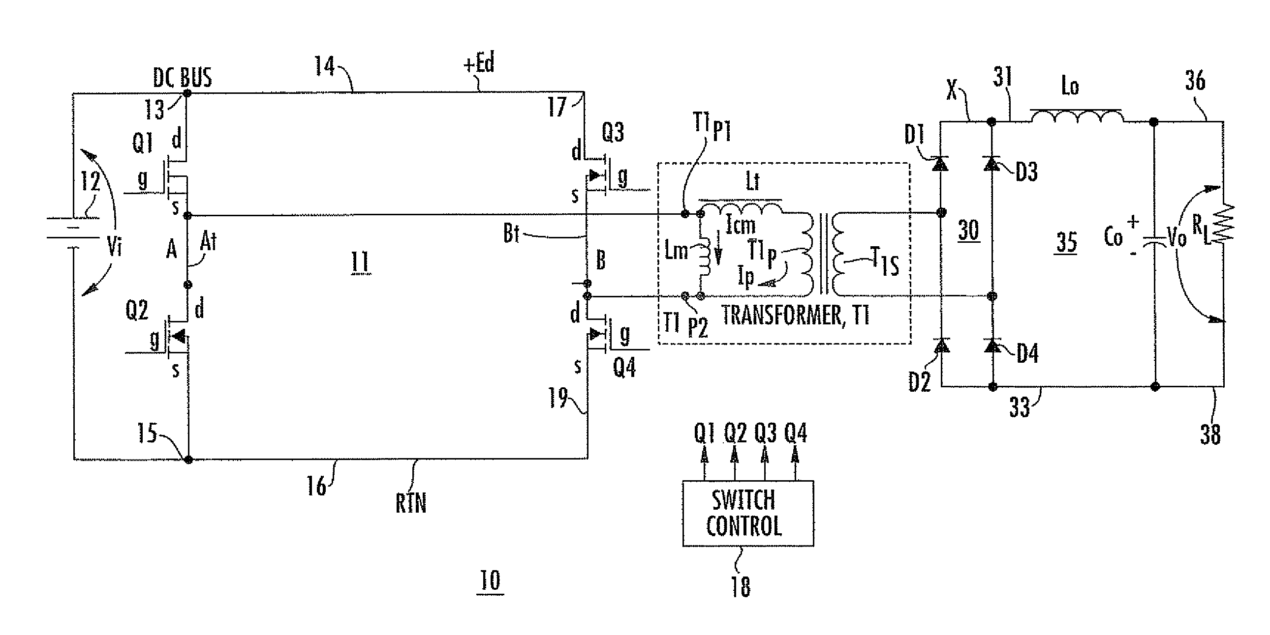
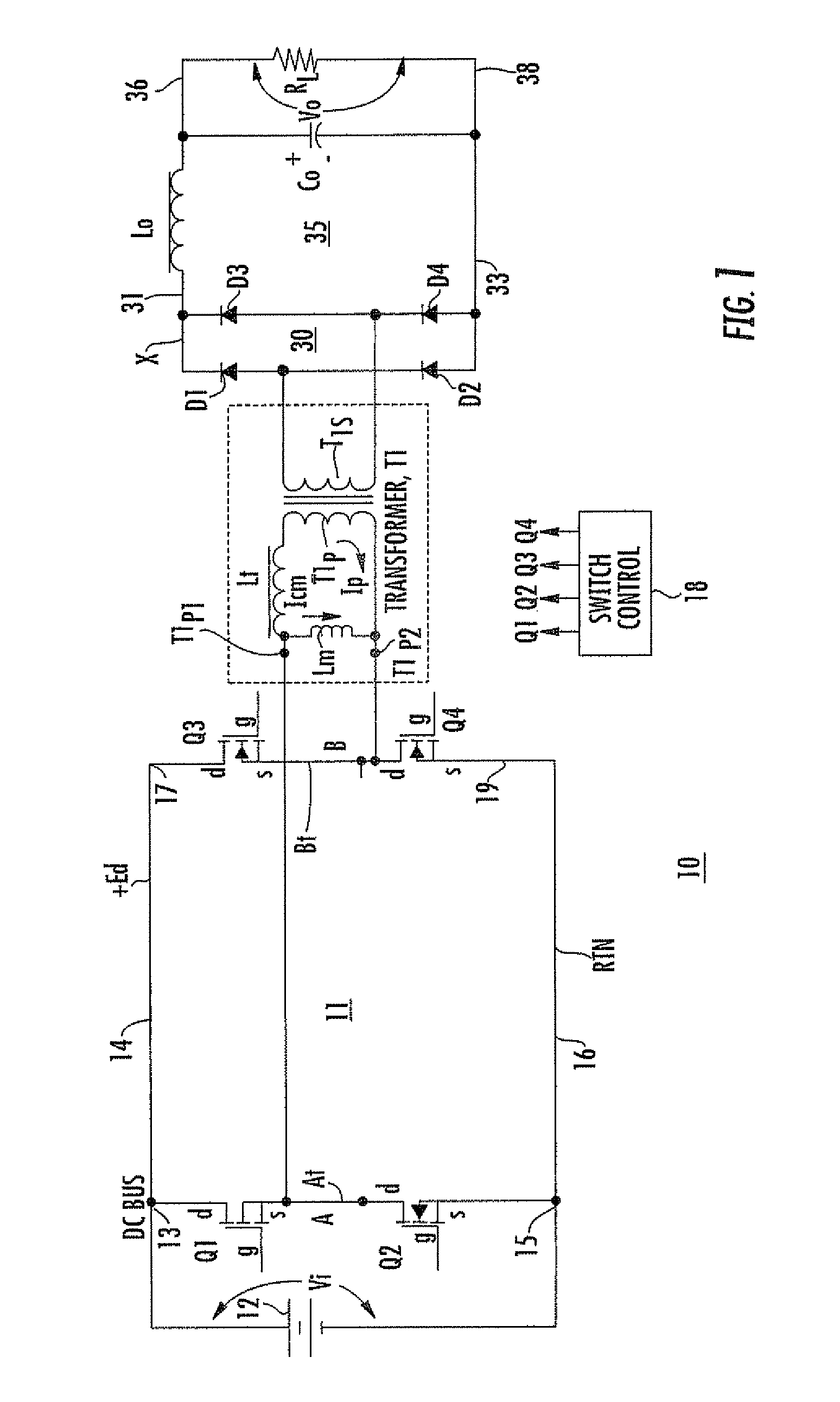
[0026]FIG. 3 is a simplified representation of the circuit of FIG. 1, illustrating certain additional elements important to consideration or understanding of overall efficiency of dc-to-dc converter. In FIG. 3, the full-wave bridge rectifier 30 of FIG. 1 is replaced for ease of understanding with a full-wave rectifier 330 including a center-tapped transformer T1 secondary winding T1s, but the same principles apply to a full-wave bridge rectifier. In FIG. 3, unidirectional current conducting devices (rectifiers or diodes) D1 and D2 of FIG. 2 have their anodes connected to the two ends of secondary winding T1s, and their cathodes connected together and by way of a conductor 31 to an end of inductor Lo of output filter 35. The diodes exhibit anode-cathode junction capacitance when in the reverse-biased state. The capacitance of diode D1 is illustrated as CD1, and the capacitance of diode D2 is illustrated as CD2. The rectified pulsating direct current from secondary winding T1s is appl...


PUM


Abstract

A power converter generates direct voltage and includes a phase-shifted PWM bridge with first and second controllable switches connected as a half-bridge with a first tap, for generating AC at the first tap. An output transformer includes a primary winding coupled to the first tap. A full-wave rectifier is connected to a secondary winding of the output transformer. A filter is coupled to the full-wave rectifier for producing filtered output direct voltage. Resonances create surges which may undesirably result in energy loss. A second transformer includes a primary winding coupled to receive the resonant surges and a secondary winding at which transformed surges appear. A second rectifier is coupled to the secondary winding of the second transformer, for rectifying the surges. The energy of the surges is returned or coupled to the source or load. In one embodiment, the full-wave rectifier is a bridge rectifier.

Description

BACKGROUND OF THE INVENTION[0001]The phase-shifted pulse-width-modulated (PSPWM) resonant bridge has become a mainstay in the dc-to-dc power converter field, because it provides low switching losses by virtue of zero-voltage switching (ZVS) at constant switching frequency. The low switching losses are very desirable, in that they allow the switching frequency to be high without undesirable heating of the switches. The high switching frequencies which ZVS allows in turn allow power converters to be made with physically small reactors such as capacitors and inductors.[0002]FIG. 1 is a simplified schematic diagram of a dc-to-dc switching converter, similar to that described in “a 1 kW 500 kHz Front-End Converter for a Distributed Power Supply System,” by Mweene et al, published in the IEEE Transactions on Power Electronics, Vol. 6, No 3, July 1991. In FIG. 1, a first source of direct energizing voltage (or electrical potential) is illustrated by a conventional battery symbol and is des...

Claims


Application Information

Patent Timeline
Patent Type & Authority Patents(United States)
IPC IPC(8): H02H7/122H02M7/5387
CPCH02M3/337H02M2001/346Y02B70/1433Y02B70/1491H02M2001/0058Y02B70/10H02M1/0058H02M1/346H02M3/33573H02M3/33571H02M3/01
Inventor SCHUTTEN, MICHAEL J.STEIGERWALD, ROBERT L.
Owner LOCKHEED MARTIN CORP
Why Eureka
Try Eureka