
Robot multi-arm control system

a multi-arm control and robot technology, applied in the field of robot multi-arm control systems, can solve the problems of specialized hardware for each of these, difficult for a robot manufacturer to provide all of the possible combinations and permutations of robot groups, and high cos

Active Publication Date: 2010-12-28
FANUC ROBOTICS NORTH AMERICA
View PDF16 Cites 14 Cited by
  • Summary
  • Abstract
  • Description
  • Claims
  • Application Information

AI Technical Summary

Benefits of technology

"The present invention provides a method and system for synchronizing the timing of events in a network of controllers, such as robots and other manipulators, that respond to electronic command signals. The method involves maintaining a count of ticks produced by a clock on each controller and exchanging information about the current tick count between the master and slave controllers. This allows for accurate synchronization of event command signals within a few milliseconds of each other. The invention also includes guide rules that define the behavior of the programs controlling motion and application processes, and can handle exceptions, forwards and backwards program execution, and motion synchronization. The technical effects of the invention include improved accuracy and efficiency in controlling industrial robots and other machines, and improved programming ease and synchronization."

Problems solved by technology

It is difficult for a robot manufacturer to provide all of the possible combinations and permutations of groups of robot manipulators and servo systems.
The hardware required for each of these is specialized and expensive.

Method used


Image

  • Robot multi-arm control system
  • Robot multi-arm control system
  • Robot multi-arm control system

Examples


Embodiment Construction

[0024]U.S. provisional patent application Ser. No. 60 / 679,919 filed May 6, 2005 is hereby incorporated herein by reference.

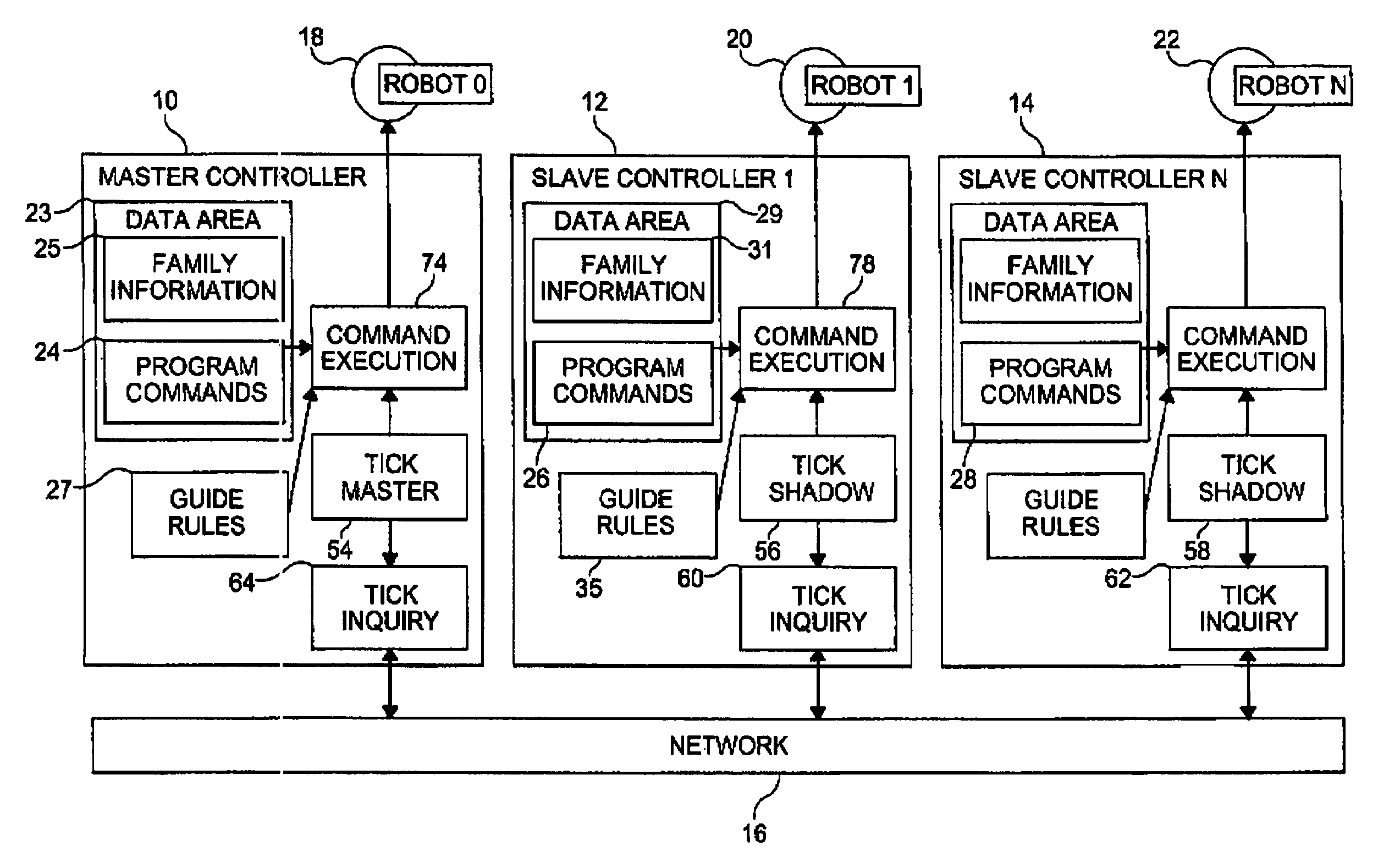
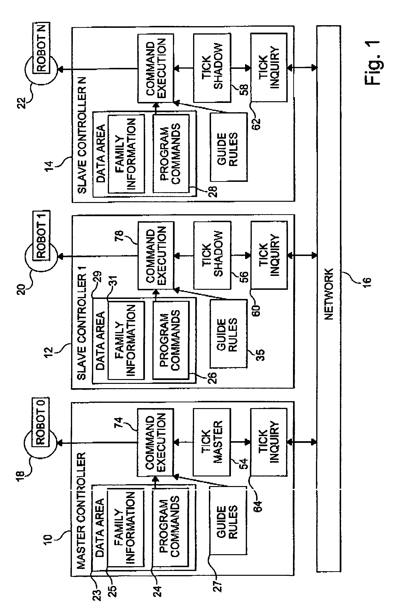
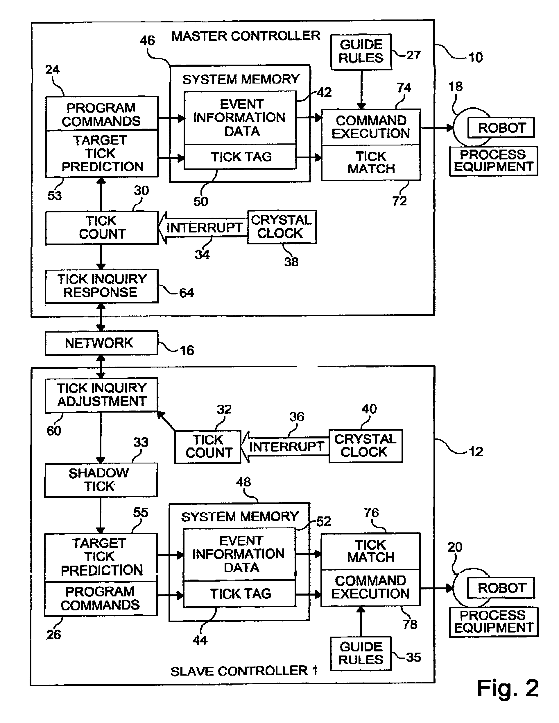
[0025]The present invention utilizes the method of synchronizing the occurrences of events in a system of controllers interconnected by a communications network described in the co-pending U.S. patent application Ser. No. 11 / 069,126, filed Mar. 1, 2005, issued Dec. 12, 2006 as U.S. Pat. No. 7,149,606, and incorporated herein by reference. Referring to FIG. 1, a system includes an indefinite number “N” of robot controllers 10, 12, 14 interconnected by a communications network 16, which may be a wireless, optical, or wired network. The controller 10 is a master controller; controllers 12, 14 are shadow controllers. Although FIG. 1 illustrates a system in which each robot controller 10, 12, 14 communicates with one robot 18, 20, 22 respectively, each controller may communicate with several robots. Movement of the robots associated with a respective controller is co...


PUM


Abstract

A robot multi-arm control system includes robot controllers that communicate via a network to transmit synchronization information from a master controller to one or more slave controllers in order to coordinate manufacturing processes. The system accounts for the network communication delay when synchronizing the event timing for process and motion synchronization.

Description

CROSS-REFERENCE TO RELATED APPLICATION[0001]This application claims the benefit of U.S. provisional patent application Ser. No. 60 / 679,919 filed May 6, 2005.BACKGROUND OF THE INVENTION[0002]The present invention relates to an apparatus and a system for controlling multiple robots in coordinated or collaborative motion.[0003]The present invention also relates to coordinating the timing of commands issuing from electronic controllers connected in a network. More particularly it pertains to actions or events performed by actuators, such as robot arms, in response to commands from a controller, which commands are synchronized with commands produced by at least one other controller.[0004]As robot systems become more sophisticated, a need arises for multiple robots to work together on a given task. For example if one robot is holding a workpiece on which another robot will perform an operation, the motions of both robots must be precisely coordinated to efficiently accomplish that task.[0...

Claims


Application Information

Patent Timeline
Patent Type & Authority Patents(United States)
IPC IPC(8): G06F19/00G06F15/16
CPCB25J9/1669B25J9/1682G05B2219/33097G05B2219/33144G05B2219/33274G05B2219/34397G05B2219/34398G05B2219/39129G05B2219/40307
Inventor YANAGITA, AKIHIROTAO, JIANMINGCHANG, TIEN L.WONG, HO CHEUNGMCGEE, H. DEANTSAI, CHI-KENGCHENG, SAI-KAINICKEL, STEVEN E.AKEEL, HADI
Owner FANUC ROBOTICS NORTH AMERICA
Learn More