Method and apparatus for reducing emissions in diesel engines

a technology for diesel engines and emissions reduction, applied in mechanical equipment, machines/engines, applications, etc., can solve the problems of increasing fuel economy, affecting the performance of diesel engines, and affecting the operation of diesel engines, etc., to achieve the effect of reducing emissions from diesel engines

Inactive Publication Date: 2011-01-04
TENNECO AUTOMOTIVE OPERATING CO INC
View PDF16 Cites 25 Cited by
  • Summary
  • Abstract
  • Description
  • Claims
  • Application Information

AI Technical Summary

Benefits of technology

[0009]Accordingly, it is an object of the present invention to provide a method and apparatus for reducing emissions from a diesel engine and particularly a small diesel engine such as the types used in passenger cars, light duty trucks, and off-road vehicles or equipment.
[0010]It is a further object of the present invention to provide a method for reducing emissions from a diesel engine using a reagent injector with a low flow rate and a high turn-down ratio (i.e., ratio between maximum injector flow rate and minimum injector flow rate).
[0011]It is a further object of the present invention to provide a method for reducing emissions from a diesel engine using a reagent injector with a flow rate that may be adjusted by electronically modifying the frequency and / or percent on time (pulse width) so as to achieve low flow rates of a reagent, especially in the range of 0.5 gr / min to 5 gr / min.
[0012]It is a further object of the present invention to provide such an apparatus with the ability to achieve higher flow rates of reagent in excess of 25 gr / min.
[0013]These and other objectives are achieved by providing a method of reducing emissions from a diesel engine including the steps of providing an injector to an exhaust outlet of the diesel engine, the injector having an orifice with a diameter of about 0.006 inch or less, providing a reagent to the injector at an inlet pressure between about 120 psi and about 60 psi, actuating the injector on and off at a frequency between about 10 Hz and about 1 Hz (e.g., 0.5 Hz) with an on-time of about 1% or more, injecting the reagent via the orifice into the exhaust outlet at an injection rate, and wherein varying at least two of the inlet pressure, the frequency, and the on-time achieves a turn-down ratio of a maximum injection rate to a minimum injection rate of at least about 31:1.

Problems solved by technology

Such engines are said to run “lean” or on a “lean mixture.” However, this increase in fuel economy is offset by undesired pollution emissions, specifically in the form of oxides of nitrogen (“NOx”).
However, use of such an aqueous urea solution involves many disadvantages.
Urea is highly corrosive and attacks mechanical components of the SCR system, such as the injectors used to inject the urea mixture into the exhaust gas stream.
Solidified urea may foul moving parts of the injector and clog any openings, rendering the injector unusable.
In addition, if the urea mixture is not finely atomized, urea deposits will form in the catalytic reactor, inhibiting the action of the catalyst and thereby reducing the SCR system effectiveness.
However, high injection pressures often result in over-penetration of the injector spray plume into the exhaust stream, causing the plume to impinge on the inner surface of the exhaust pipe opposite the injector.
Over-penetration leads to inefficient use of the urea mixture and reduces the range over which the vehicle can operate with reduced NOx emissions.
Further reduction in orifice size, while possible, may become impractical from a production perspective due to limits of orifice durability and machineability as the diameter of the exit orifice becomes less than 0.006 of an inch.

Method used


Image

  • Method and apparatus for reducing emissions in diesel engines
  • Method and apparatus for reducing emissions in diesel engines
  • Method and apparatus for reducing emissions in diesel engines

Examples


Embodiment Construction

[0027]The ensuing detailed description provides exemplary embodiments only, and is not intended to limit the scope, applicability, or configuration of the invention. Rather, the ensuing detailed description of the exemplary embodiments will provide those skilled in the art with an enabling description for implementing an exemplary embodiment of the invention. It should be understood that various changes may be made in the function and arrangement of elements without departing from the spirit and scope of the invention as set forth in the appended claims.

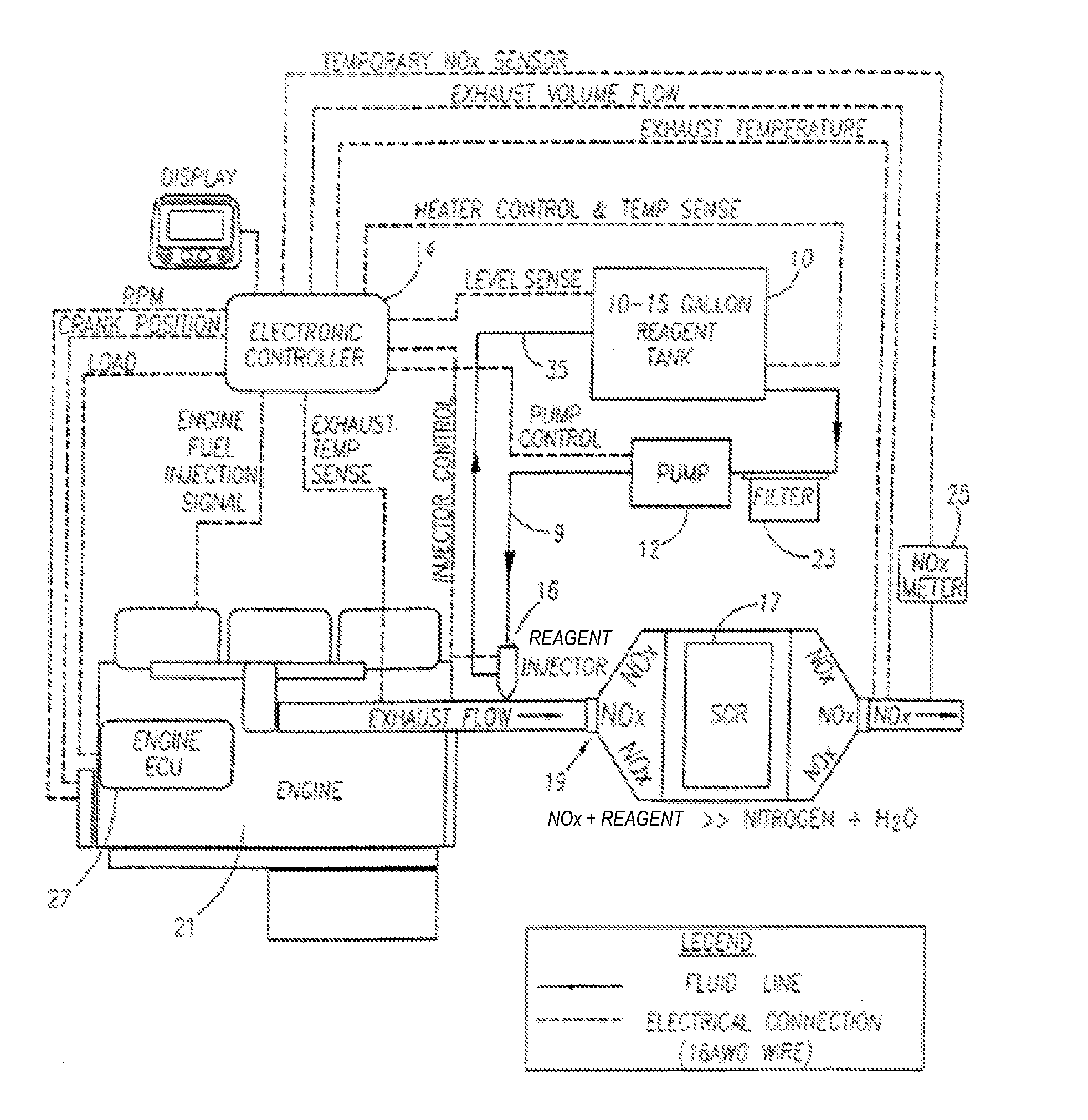
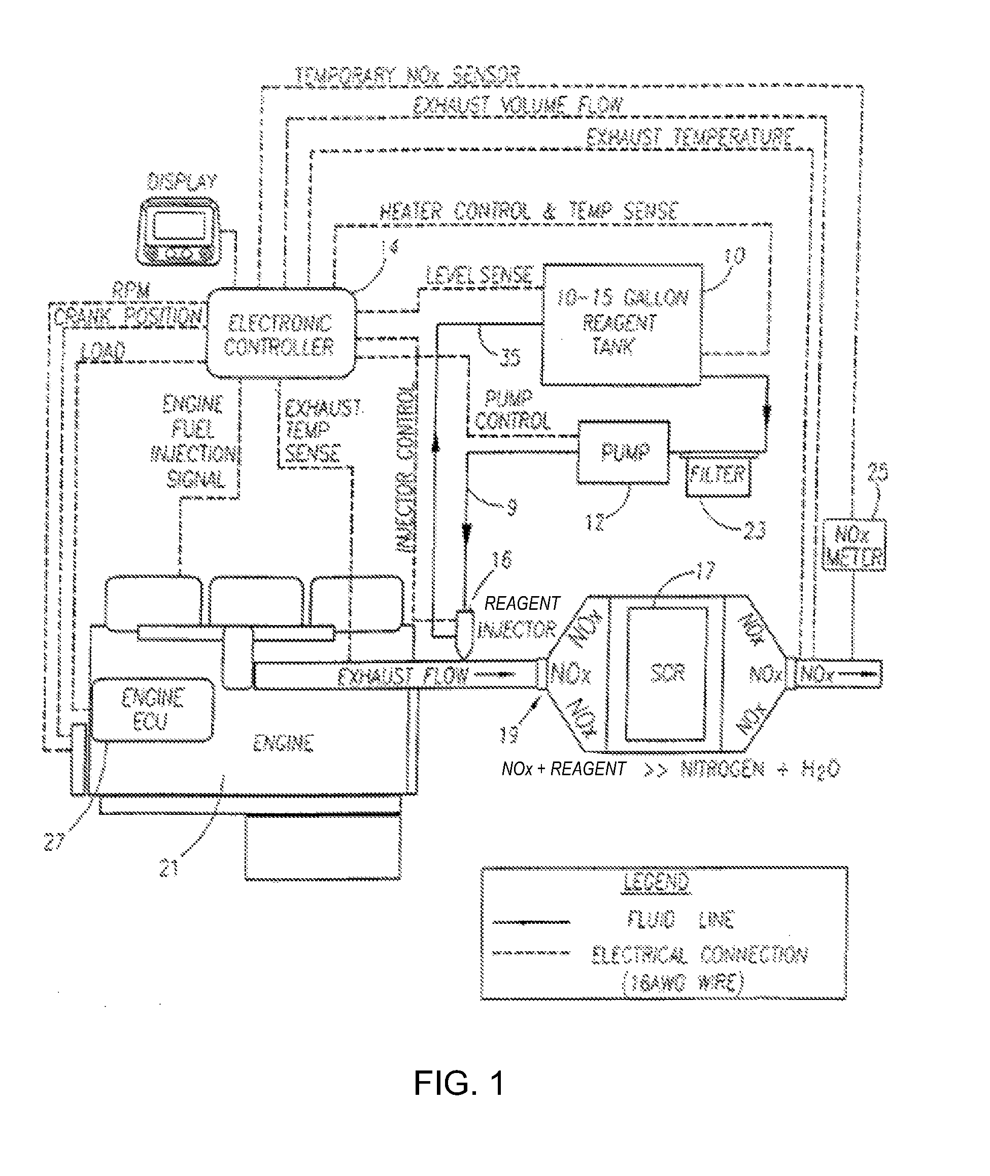
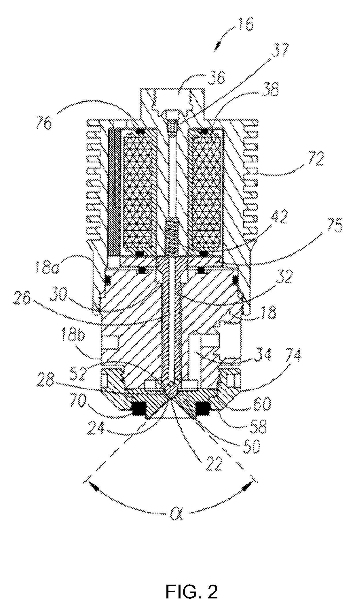
[0028]The present invention provides a low flow rate injector for diesel emissions control, and methods for injecting a reagent at low flow rates.

[0029]The present invention achieves lower flow rates in a commercial injector of the type disclosed in commonly owned co-pending U.S. patent application Ser. No. 11 / 112,039 entitled Methods and Apparatus for Injecting Atomized Fluid, filed on Apr. 22, 2005 (U.S. Published Application No. 2...


PUM

PropertyMeasurementUnit
diameteraaaaaaaaaa
inlet pressureaaaaaaaaaa

Abstract

A method of reducing emissions from a diesel engine including the steps of providing an injector to an exhaust outlet of the diesel engine, the injector having an orifice with a diameter of about 0.006 inch or less, providing a reagent to the injector at an inlet pressure between about 120 psi and about 60 psi, actuating the injector on and off at a frequency between about 10 Hz and about 1 Hz with an on-time of about 1% or more, injecting the reagent via the orifice into the exhaust outlet at an injection rate, and wherein varying of at least two of the inlet pressure, the frequency, and the on-time achieves a turn-down ratio of a maximum injection rate to a minimum injection rate of at least about 31:1.

Description

CROSS-REFERENCE TO RELATED APPLICATIONS[0001]This application claims priority under 35 §U.S.C. 119(e) to the U.S. Provisional Application No. 60 / 809,918, filed on May 31, 2006. This application also claims priority under 35 §U.S.C. 120 to U.S. patent application Ser. No. 11 / 714,718, filed on Mar. 5, 2007, which is a continuation-in-part of U.S. patent application Ser. No. 11 / 112,039, filed on Apr. 22, 2005, which claims priority under 35 §U.S.C. 119(e) to U.S. Provisional Application No. 60 / 565,356, filed Apr. 26, 2004.FIELD OF THE INVENTION[0002]The present invention relates generally to the reduction of emissions produced by lean burn engines. In particular, the present invention provides methods and apparatus for injecting a reagent, such as an aqueous urea solution, into an exhaust stream in order to reduce oxides of nitrogen (“NOx”) emissions from diesel engine exhaust. More particularly, the present invention provides a low flow rate injector for diesel emissions control, and ...

Claims


Application Information

Patent Timeline
Patent Type & Authority Patents(United States)
IPC IPC(8): F01N3/00
CPCF01N3/2066F01N9/00F01N3/208Y02T10/24F01N2560/026F01N2560/06F01N2560/07F01N2560/08F01N2610/02F01N2610/03F01N2610/10F01N2610/11F01N2610/14F01N2610/1453F01N2610/146F01N2900/0408F01N2900/0411F01N2900/08F01N2900/1808F01N2900/1812F01N2900/1814Y02T10/47Y02T10/12Y02T10/40F01N3/28F01N3/10F01N3/00
Inventor BRODERICK, R. GIFFORDELDREDGE, TOM
Owner TENNECO AUTOMOTIVE OPERATING CO INC
Why Eureka
Try Eureka