Chair

a technology for chairs and backrests, applied in the field of chairs, can solve the problems of deformation inability to make only a left side or a right side portion of the backrest surface move backward, and the conventional chair does not take into account the following, so as to reduce the load applied, reduce the curvature, and increase the distance between the frame elements

Inactive Publication Date: 2011-01-04
KOKUYO CO LTD
View PDF92 Cites 47 Cited by
  • Summary
  • Abstract
  • Description
  • Claims
  • Application Information

AI Technical Summary

Benefits of technology

[0008]In order to solve the problem mentioned above, in accordance with the present invention, there is provided a chair comprising a backrest in which an upper portion of a backrest surface is supported by a plurality of frame elements arranged so as to be spaced with each other in a width direction, wherein the respective frame elements are independently movable backward and forward. In this case, the backrest surface means generally a structure which is structured by an element such as an upholstery member, a cushion member or the other members, and supports a body of a sitting person so as to receive a load thereof. Further, “independently movable backward and forward” means that one frame element can be relatively displaced with respect to the other frame element in a backward and forward direction. The structure mentioned above can make only a left half portion of the upper portion of the backrest surface or only a right half portion displace backward. Further, it is possible to three-dimensionally displace the shape of the backrest surface while following the motion of the sitting person such as the sitting person looks around or the like, and it is possible to achieve the chair having an improved comfortable sitting feeling which can preferably keep supporting the body of the sitting person without vainly limiting the motion of the sitting person.
[0010]In order to achieve the chair which can selectively execute a motion of integrally tilting an entire of the backrest surface and a motion of tilting only an upper portion of the backrest surface, it is simple to structure such that one of the upper frame elements can be relatively tilted backward with respect to the other by coupling the upper frame elements to the lower frame elements via hinges.
[0011]If the structure is made such that a reaction force frame element is provided so as to be connected to a back surface of a frame element supporting an upper portion of the backrest surface and accumulate a reaction force based on an elastic deformation, and the frame element is supported from behind by the reaction force frame element, it is not necessary that a coil spring or the like is interior provided in the inside of the hinge portion, and it is possible to prevent the hinge portion from being enlarged. In addition, it is possible to prevent an uncomfortable feeling from being applied to an existence of the reaction force frame element by forming the reaction force frame element as an outer appearance like a part of the back frame, and it is possible to keep beauty and elegance as a furniture.
[0013]If the lateral bridging member is assembled in a state of achieving an initial elastic force such as to move the frame elements away from each other in the width direction, against the matter that the load is applied to the backrest surface and the frame elements tend to fall down to the inner side, it is possible to cancel and reduce the load applied to the frame elements and the hinges.
[0015]In addition, the backrest surface is structured by attaching an elastically deformable upholstery member on front surfaces of the plurality of frame elements, whereby it is possible to provide a soft sitting feeling having a reduced load by deforming while following various motions of the sitting person and fitting to a wide range of the body.
[0016]In accordance with the present invention, it is possible to achieve the seat which can three-dimensionally change the shape of the backrest surface while following the motion of the sitting person such as looking around while sitting or the like.

Problems solved by technology

However, the conventional chair does not take into consideration following the motion of the sitting person.
However, in the existing chair such as the example mentioned above, since both the right and left frame elements are rigidly coupled to each other via a lateral bridging member, and these frame elements are integrally moved backward and forward, it is impossible to make only a left side portion or a right side portion of the backrest surface displace backward.
Accordingly, it is impossible to deform the backrest surface while following the motion such as the sitting person looks around or the like, and a motion of the sitting person is limited.

Method used


Image

  • Chair
  • Chair
  • Chair

Examples


Embodiment Construction

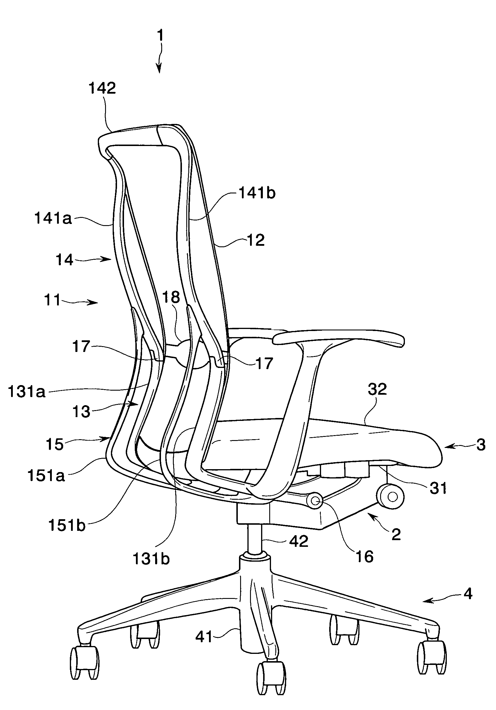
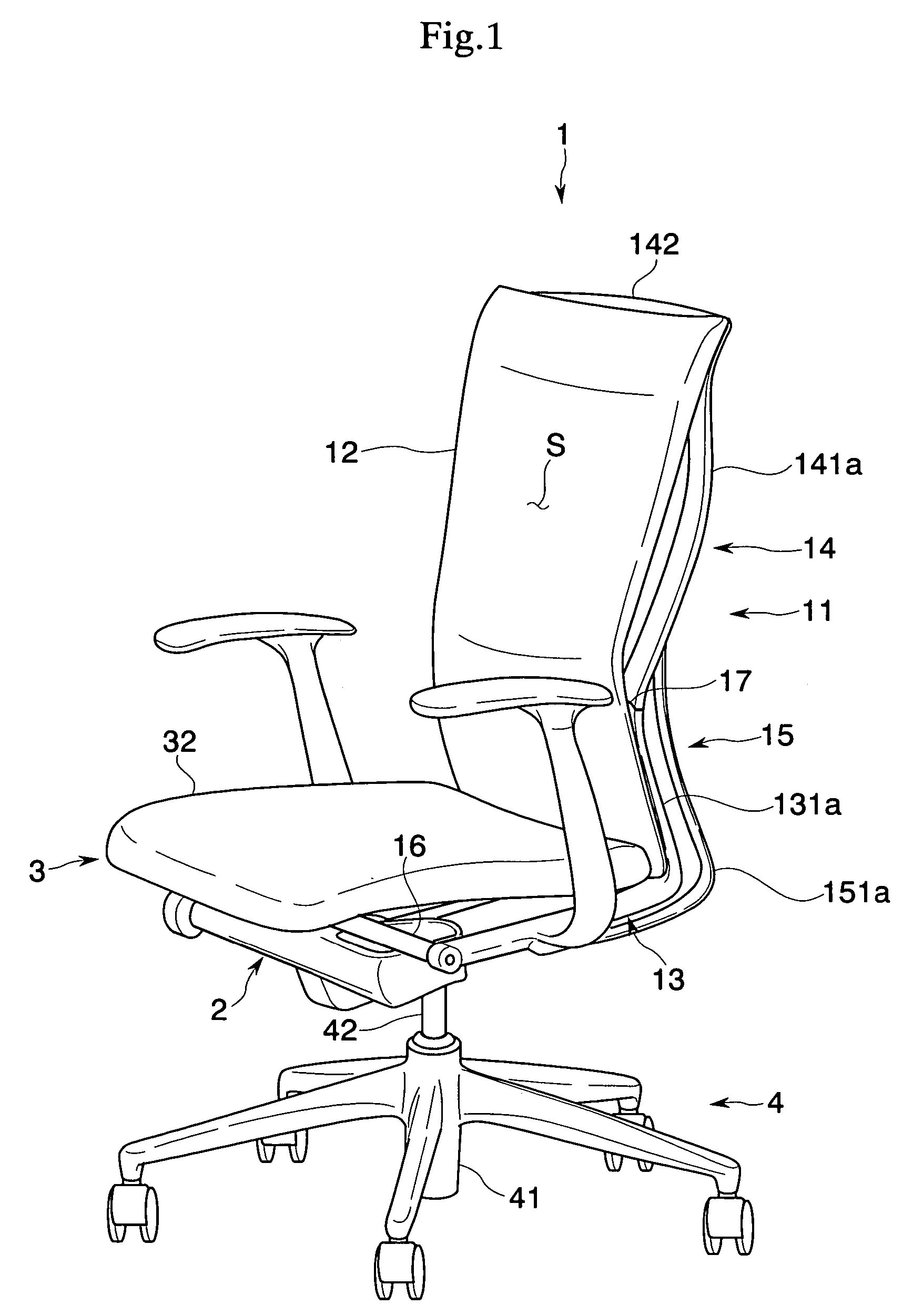
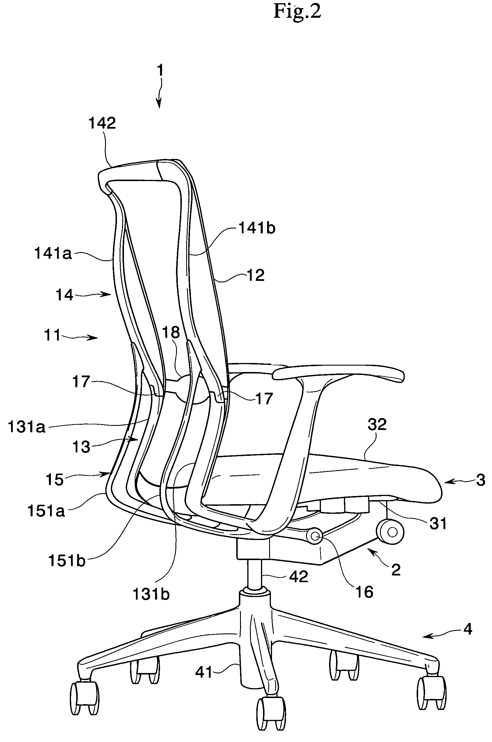
[0035]A description will be given below of an embodiment in accordance with the present invention with reference to the accompanying drawings. A chair in accordance with the present embodiment is provided with a leg body 4, a base body 2 supported by a leg body 4, a seat 3 arranged on the base body 2, and a backrest 1 pivoted to the base body 2 via a horizontal supporting shaft 16, as shown in FIGS. 1 to 5, and is structured such that the seat 3 and the backrest 1 are tilted in an interlocking manner, whereby a synchronized rocking motion can be executed.

[0036]In detail speaking, the leg body 4 is provided with a leg wing 41 to which a plurality of casters are installed, and a leg support pillar 42 uprising approximately vertically from a center of the leg blade 41, and the leg support pillar 42 can be protruded and contracted up and down based on expansion and contraction of a gas spring (not shown) interposed between the leg wing 41 and the leg support pillar 42.

[0037]The base bod...


PUM


Abstract

The invention achieves a chair in which a shape of a backrest surface can be three-dimensionally changed while following a motion such as a sitting person looks around while sitting or the like. In a chair provided with a backrest in which an upper portion of a backrest surface is supported by a plurality of frame elements arranged so as to be spaced with each other in a width direction, the respective frame elements are independently movable backward and forward.

Description

BACKGROUND OF THE INVENTION[0001]1. Field of the Invention[0002]The present invention relates to a chair in which a shape of a backrest surface can be three-dimensionally changed while following a motion of a body of a person sitting thereon.[0003]2. Description of the Related Art[0004]There has been known a chair in which a backrest surface is structured by bridging an upholstery member between a pair of frame elements formed in both right and left sides. For example, Japanese Unexamined Patent Publication No. 2002-119375 and Japanese Unexamined Patent Publication No. 2002-119373 disclose a chair in which an upper portion of a backrest surface is supported by an upper frame element, a lower portion of the backrest surface is supported by a lower frame element, and the backrest surface can be formed in correspondence to a body type and a backbone shape of a sitting person through a rotating operation of the upper frame element and a rotating operation around a horizontal axis of the...

Claims


Application Information

Patent Timeline
Patent Type & Authority Patents(United States)
IPC IPC(8): A47C1/032
CPCA47C1/03255A47C1/03261A47C7/40A47C7/445A47C31/023A47C7/4454
Inventor UEDA, NOBUYUKI
Owner KOKUYO CO LTD
Why Eureka
Try Eureka