
Propulsion arrangement

a technology of propulsion arrangement and arrangement, which is applied in the direction of vessel auxiliary drive, vessel parts, vessel construction, etc., can solve the problems of not being able to function as electric motor, generator cannot provide power through engine, and requiring additional equipment, so as to reduce transmission losses, simplify the arrangement, and reduce costs

Inactive Publication Date: 2011-01-04
WARTSILA FINLAND OY
View PDF15 Cites 24 Cited by
  • Summary
  • Abstract
  • Description
  • Claims
  • Application Information

AI Technical Summary

Benefits of technology

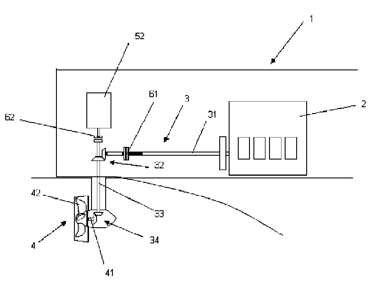
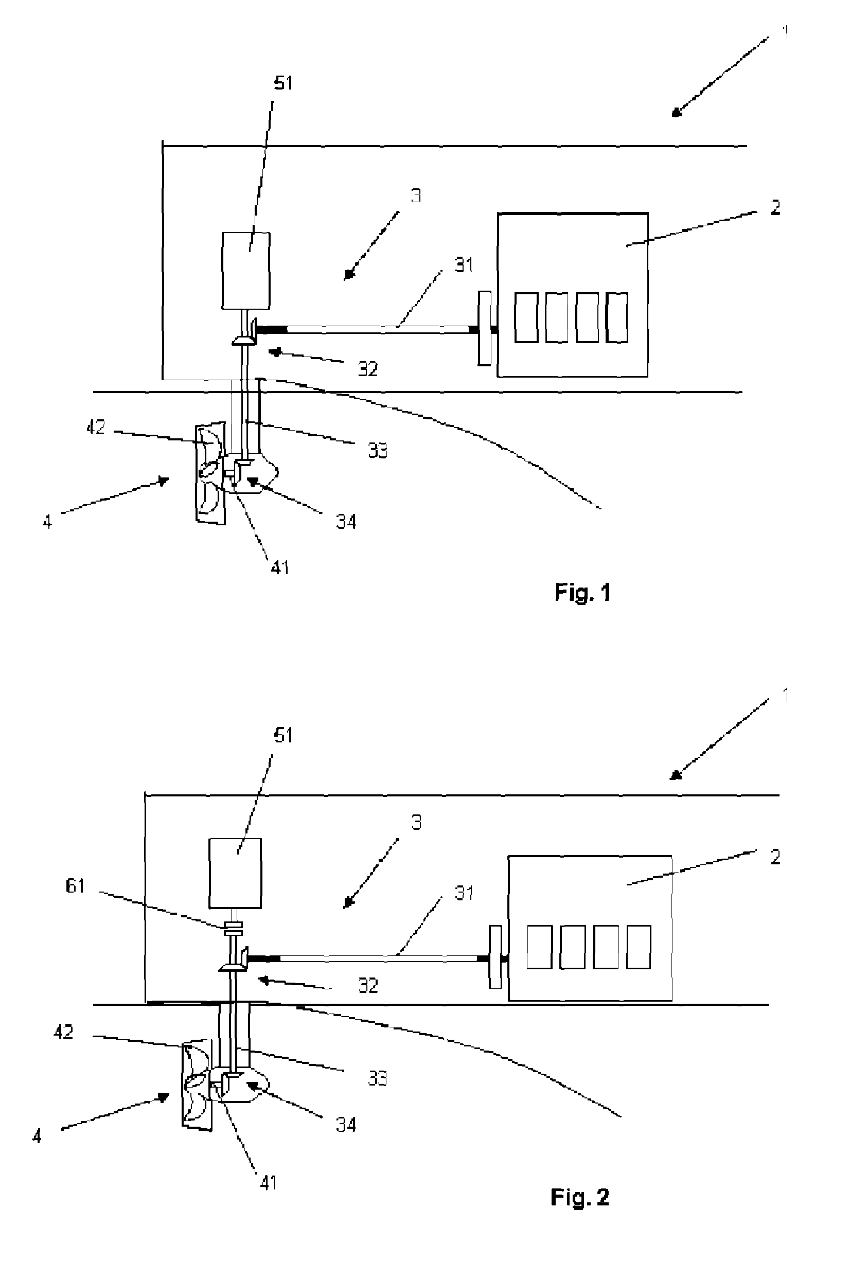
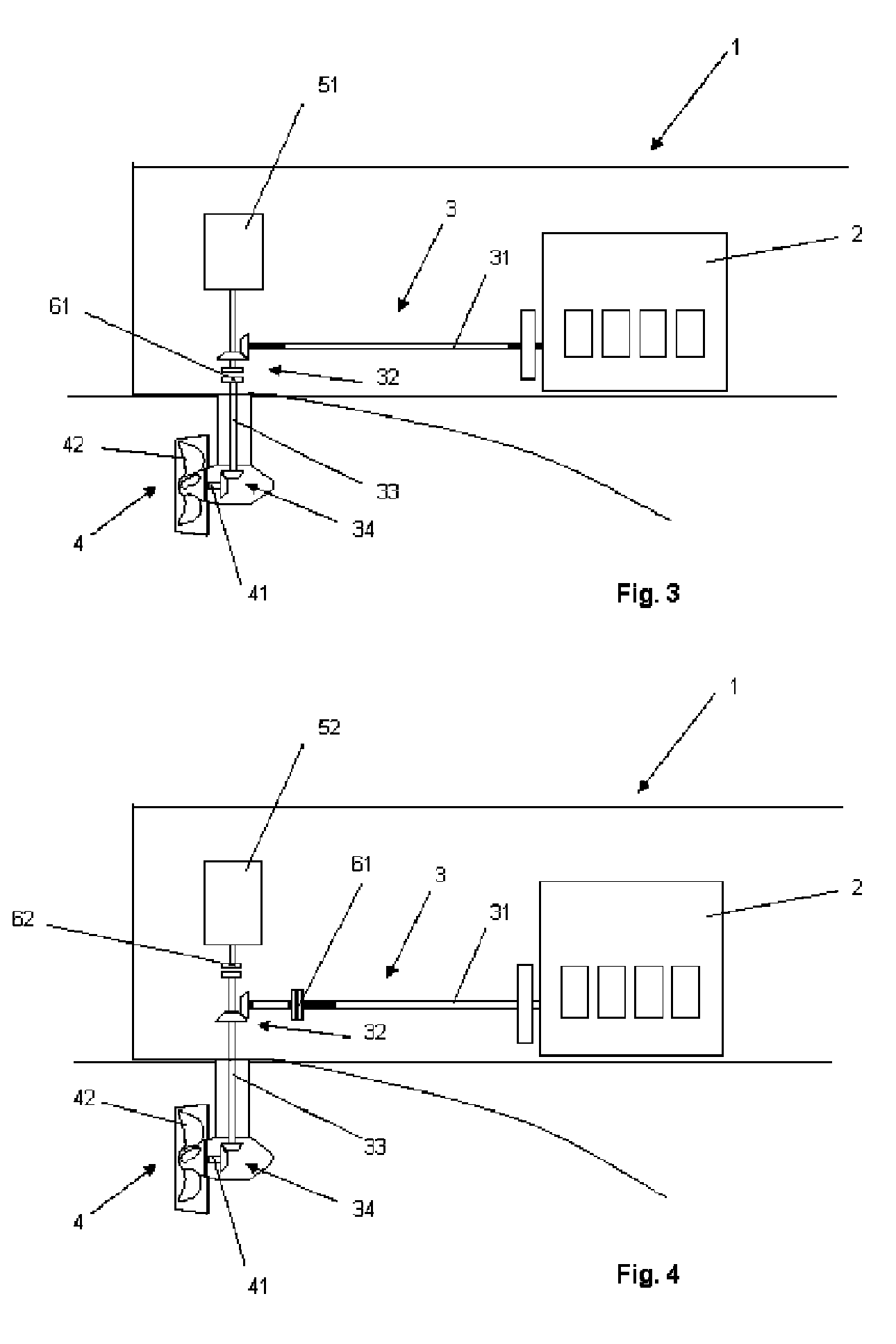
[0008]The basic idea of the invention is to provide a propulsion system that includes an electric generator or a combined electric generator and motor and that may be directly employed also to the steerable thruster unit. This is realised by means of a propulsion arrangement, in which the shaft arrangement comprises a main shaft extending from the internal combustion engine to a first angle gear and a drive shaft extending from the first angle gear to a second angle gear in the steerable thruster unit. The electric generator or the combined electric generator and motor is connected to the drive shaft of the shaft arrangement, after the main shaft and the first angle gear connected thereto. The main shaft is thus free of any installations relating to the electric generator or the combined electric generator and motor.
[0009]According to an advantageous embodiment of the invention the electric generator is directly coupled to the drive shaft, above the first angle gear with respect to the steerable thruster unit. This eliminates any space requirements around the internal combustion engine or the main shaft.
[0010]According to another advantageous embodiment of the invention the electric generator is directly coupled to the drive shaft, above the first angle gear with respect to the thruster unit, and a coupling is provided on the drive shaft, between the electric generator and the first angle gear. In addition, this allows the internal combustion engine to drive the steerable thruster unit without turning the generator.
[0011]According to another advantageous embodiment of the invention the electric generator is directly coupled to the drive shaft, directly above the first angle gear with respect to the steerable thruster unit, and a coupling is provided on the drive shaft between the first angle gear and the second angle gear. In addition, this allows the internal combustion engine to turn the electric generator without driving the steerable thruster unit.
[0019]This simplifies the arrangements discussed above and reduces costs. Transmission losses also are reduced when the arrangements are used to drive the steerable thruster unit. No space is needed along the main shaft or at the free end of the internal combustion engine. On a whole, the invention also reduces the equipment on board the marine vessel.

Problems solved by technology

This solution requires surplus space at the free end of the engine.
Furthermore, such a generator can not provide power through the engine, i.e. it can not function as an electric motor.
Naturally the step-up gear necessitates additional equipment with thereto related costs.
The step-up gear also causes transmission losses.
Furthermore, this known solution requires sufficient and suitable space along the main shaft.

Method used


Image

  • Propulsion arrangement
  • Propulsion arrangement
  • Propulsion arrangement

Examples


Embodiment Construction

[0027]In the figures a marine vessel is generally indicated by reference numeral 1. The marine vessel 1 is provided with a propulsion arrangement comprising an internal combustion engine 2, typically a diesel engine, a shaft arrangement 3 and a steerable thruster unit 4. The shaft arrangement 3 includes a main shaft 31 extending from the internal combustion engine 2 to a first angle gear 32, which connects the main shaft 31 to a drive shaft 33, and a second angle gear 34 arranged in the steerable thruster unit 4. The second angle gear 34 connects the drive shaft 33 to a propeller shaft 41, with a propeller 42, in the steerable thruster unit 4.

[0028]Power is thus transmitted from the internal combustion engine 2 by means of the substantially horizontal or generally horizontally oriented main shaft 31 to the first angle gear 32, from the first angle gear 32 to the substantially vertical or generally vertically oriented drive shaft 33, which drives the second angle gear 34, which in tu...


PUM


Abstract

The present invention relates to a propulsion arrangement for a marine vessel, which propulsion arrangement comprises an internal combustion engine, a shaft arrangement and a steerable thruster unit. The marine vessel further comprises an electric generator or a combined electric generator and motor in connection with the propulsion arrangement. In order to reduce space requirements and required equipment as well as to raise efficiency, the shaft arrangement comprises a main shaft extending from the internal combustion engine to a first angle gear and a drive shaft extending from the first angle gear to a second angle gear in the steerable thruster unit. The electric generator or the combined electric generator and motor is connected to the drive shaft of the shaft arrangement after the main shaft and the first angle gear are connected thereto.

Description

[0001]This is a national stage application filed under 35 USC 371 based on International Application No. PCT / FI2005 / 050432 filed Nov. 23, 2005, and claims priority under 35 USC 119 of Finnish Patent Application No. 20055109 filed Mar. 10, 2005.BACKGROUND OF THE INVENTION[0002]The present invention relates to a propulsion arrangement for a marine vessel, which propulsion arrangement comprises an internal combustion engine, a shaft arrangement and a steerable thruster unit, whereby the marine vessel further comprises an electric generator or a combined electric generator and motor in connection with the propulsion arrangement.[0003]Conventional marine vessels with the above type of propulsion arrangements and thereto related machinery may be provided with an additional device, particularly an electric generator or a combined electric generator and motor for generating e.g. hotel load electric power or for improving flexibility and redundancy in propulsion power. Such devices are often...

Claims


Application Information

Patent Timeline
IPC IPC(8): B63H5/125B63HB63H21/20B63H23/18B63H23/30B63J3/02
CPCB63H5/125B63H21/20B63H23/18B63J3/02B63H23/30Y02T70/5236B63H2005/1256B63H2021/205
Inventor LEVANDER, OSKARHANNULA, SUSANNA
Owner WARTSILA FINLAND OY
Learn More