Surgical positioners

a surgical and positioner technology, applied in the field of surgical positioners, can solve the problems of reducing the precision of surgical procedures, affecting the accuracy of surgical procedures, so as to improve the precision with which surgical procedures are performed, and increase surgical precision

Inactive Publication Date: 2011-01-04
SMITH & NEPHEW INC
View PDF580 Cites 43 Cited by
  • Summary
  • Abstract
  • Description
  • Claims
  • Application Information

AI Technical Summary

Benefits of technology

[0015]Various aspects and embodiments of the present invention include surgical positioners capable of increasing surgical precision, as well as methods and procedures for utilizing the surgical positioners. These surgical positioners include certain platforms, which are securable to an individual's anatomy, each other, and / or any other desired structure. These platforms may be modular in nature, allowing various surgical items to be secured and / or stabilized in various orientations and locations. They provide stable bases for locating surgical items, including surgical references useful in conjunction with image-guided surgical navigation systems (“tracking systems”), such as the systems discussed above. These platforms may also be used as stable bases for other surgical instruments, used with or without tracking systems, including drills, reamers, surgical guides or any other desired instrumentation. These platforms may also be used to guide the installation of surgical implants, such as intramedullary nails. Consequently, various embodiments of the present invention allow ease of securing, locating, mounting, stabilizing, navigating, targeting, positioning and / or aligning surgical items relative to an individual's anatomy, thereby improving the precision with which surgical procedures may be performed.

Problems solved by technology

For example, in orthopedic procedures, less than optimum alignment of implanted prosthetic components may cause undesired wear, which may eventually lead to the failure of the implanted prosthesis and necessitate revision.
With orthopedic procedures, previous practices have made precise alignment of prosthetic components challenging.
For example, in a total knee arthroplasty, previous instrument design for resection of bone limited the alignment of the femoral and tibial resections to average values for varus / valgus, flexion / extension and external / internal rotation.
Additionally, surgeons often use visual landmarks or “rules of thumb” for alignment, which can be misleading due to anatomical variability.
Intramedullary referencing instruments are also undesirable because they violate the femoral and tibial canals, increasing the risk of fat embolism and unnecessary blood loss in the patient.
Similar problems may also be encountered in other procedures, such as the replacement of hip and shoulder joints as well as the insertion of an intramedullary canal nail into a weakened or broken bone.
Even minor changes in orientation and / or position of the references may lead to dramatic differences in how the system detects the orientation and / or location of the associated anatomy or instruments.
Such changes may require the system to be recalibrated, requiring additional fluoroscopy or other imaging to be obtained, increasing the time and the expense of the procedure.
Failure to recalibrate the system may lead to imprecision in the execution of the desired surgical procedure.
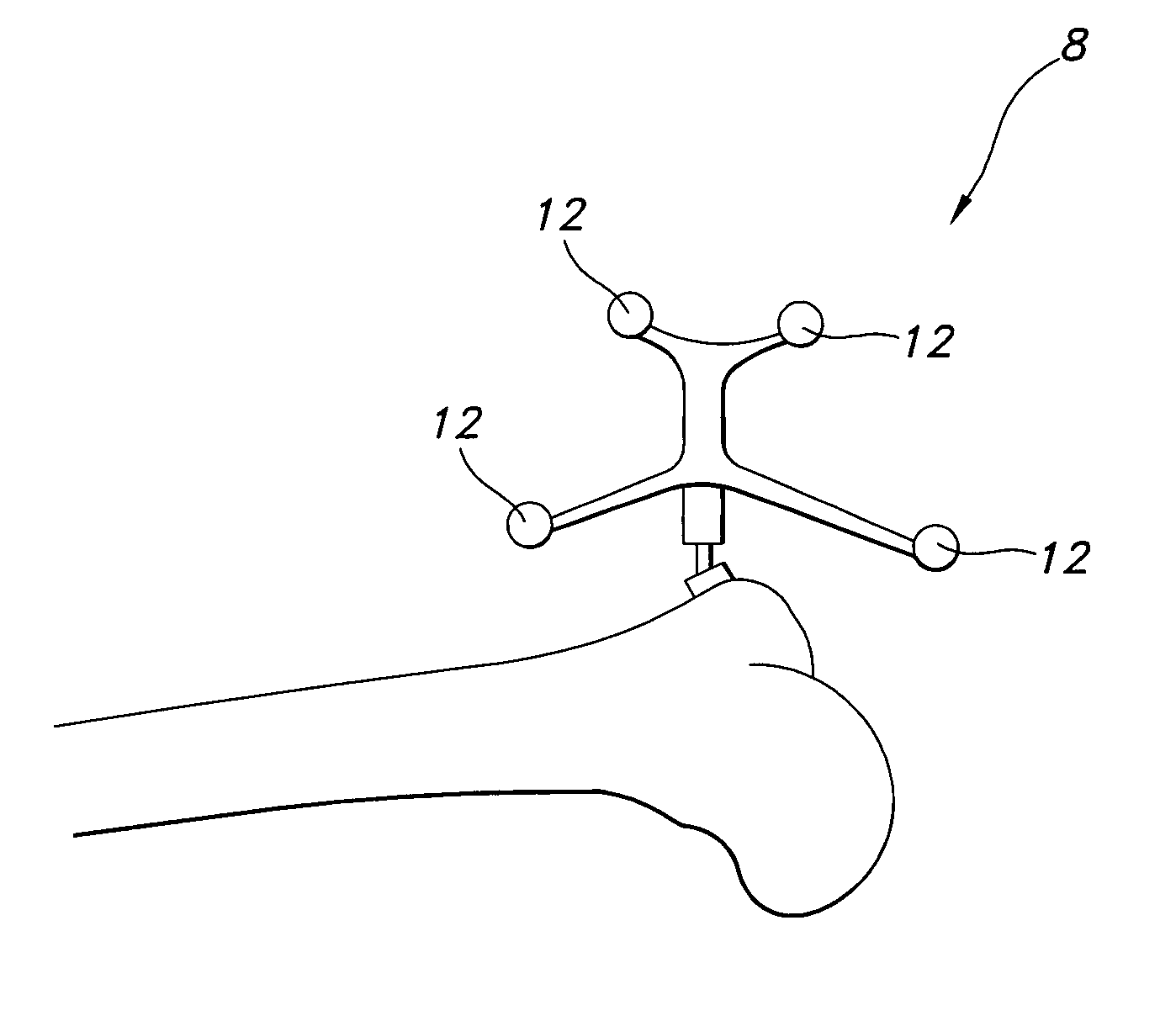
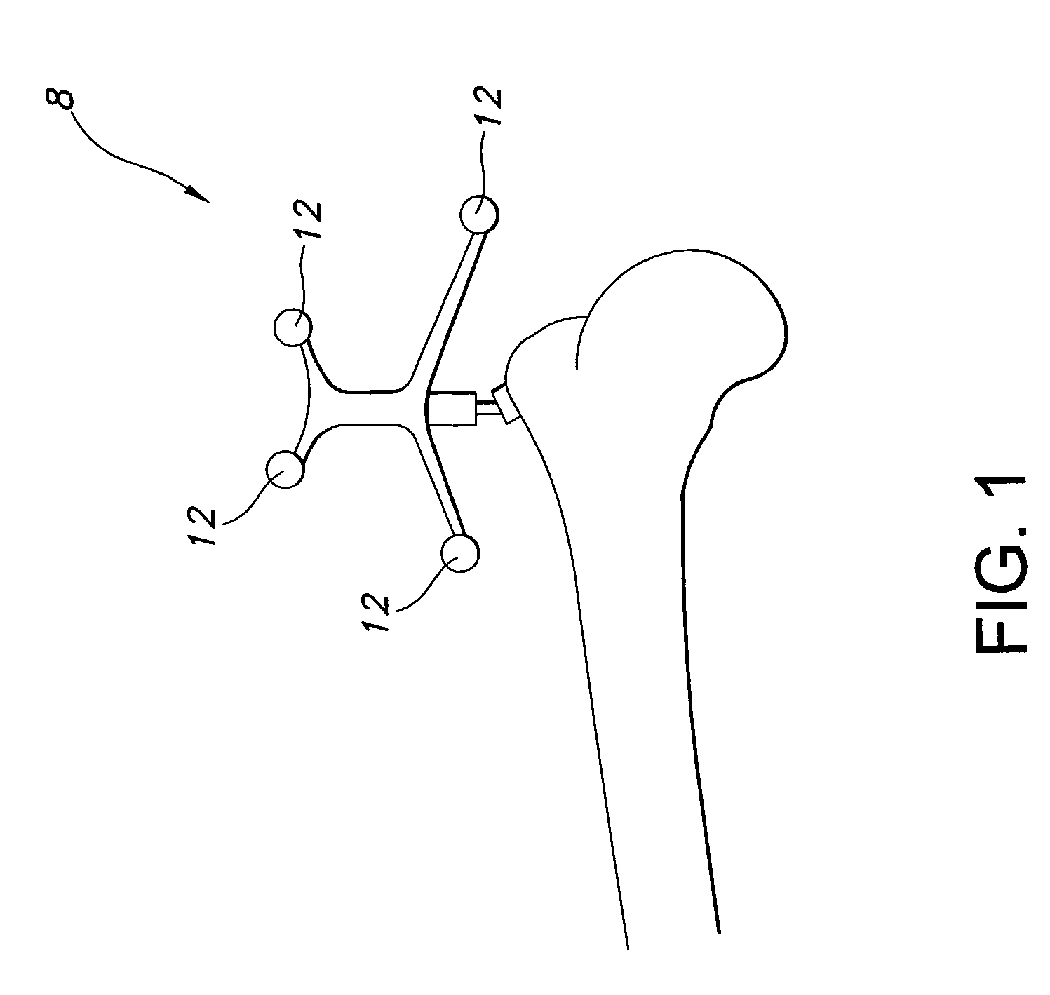
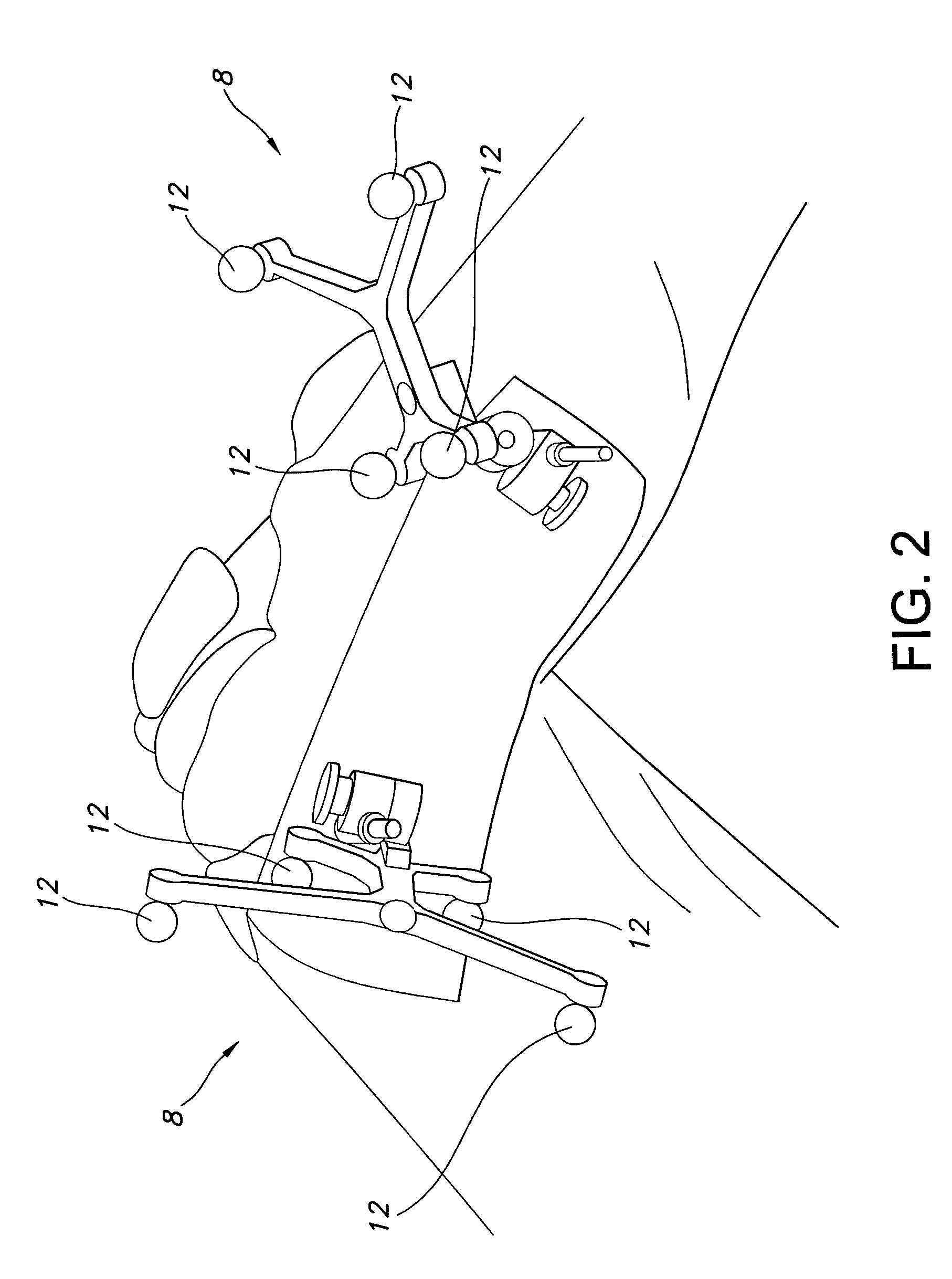
The references 8 and 10 shown in FIGS. 1-3 may be undesirable because they may be particularly vulnerable to change of location and / or orientation with respect to their associated instrument or anatomy.
This may be especially problematic in busy operating rooms, where several people are working at once.
References 8 and 10 may be particularly susceptible to being bumped, dislodged, or otherwise misplaced because they are cumbersome and prone to interfering with the surgical procedure because of their size.
The references may also be susceptible to change in location and / or orientation because they are secured at a single location by a column or other structure to the bony anatomy, instruments, or other structure and are distanced from the anatomy to which they are attached.
Some reference structures do not allow the repositioning or removal of individual fiducials with respect to the reference structure.
This may be problematic because there may be times when it is desirable to place the reference structure in a location and orientation that can be effectively visualized and tracked by the system, yet remain out of the way of the surgeon.
Moreover, reference structures that do not allow removal of the fiducials from the remainder of the reference structure prevent defective or inoperative fiducials from being replaced without replacing the entire reference structure.
Problematically, during surgery a surgeon may need to use one hand to stabilize an instrument while using the other hand to target, align and / or navigate the instrument.
If the surgeon is the sole means for stabilizing as well as aligning / navigating / targeting the instrument, distractions to the surgeon may result in the instrument becoming misaligned, increasing the chances for surgical error and / or increasing procedural tedium.
For instance, if the surgeon looks away from the instrument to view a monitor, the surgeon may inadvertently move his or her hands, causing the instrument to move relative to the anatomy.
However, robotic arms may require the navigation of the instrument to be programmed and consequently executed without surgeon input during the robotic portion of the procedure.
These robotic arms may be undesirable because they prevent the surgeon from using his or her intuition and experience to target, align and / or navigate the instrument.
In addition, robots generally operate much more slowly than a skilled surgeon.
In addition to the other problems mentioned above, some previous instrument mounting arms may be undesirable because readjustment of the instrument, once locked into place, requires unlocking the arm.
Unlocking the arm may increase the tedium of the procedure.

Method used


Image

  • Surgical positioners
  • Surgical positioners
  • Surgical positioners

Examples


Embodiment Construction

[0069]FIG. 4 shows a platform 14 according to various aspects and embodiments of the present invention. The platform 14 may be used as a stabilizer platform by being biased against portions of an individual's anatomy to provide a stable and low profile platform for securing other items that may be useful in various surgical procedures. Items may be secured to or stabilized by stabilizer platform 14 in a releasable, rigid and / or movable manner.

[0070]Stabilizer platform 14 may be formed from any desired and suitable material and in any desired and suitable method. For instance, in some embodiments, stabilizer platform 14 may be formed from high impact, vacuum molded plastic. In other embodiments, stabilizer platform 14 may be machined from stainless steel or aluminum.

[0071]Any desired item may be supported by stabilizer platform 14. Various items that may be supported by stabilizer platform 14 include, but are not limited to, reference transmitters (such as the reference transmitter 1...


PUM


Abstract

Surgical positioners may include platforms, surgical item positioners and / or surgical references as well as methods for using stabilizer platforms, surgical item positioners and / or surgical references. Stabilizer platforms may include low profile platforms rigidly mounted to portions of an individual's anatomy. Various items may be secured and / or stabilized by the stabilizer platform, including support platforms as well as surgical references. Support platforms may stabilize and assist surgeons in using, navigating, aligning and positioning surgical items. Surgical references may include modular fiducial systems that may be secured to stabilizer platforms, support platforms, surgical items and / or directly to portions of an individual's anatomy.

Description

BACKGROUND[0001]A major concern during surgical procedures as well as other medical operations is carrying out the procedures with as much precision as is possible. For example, in orthopedic procedures, less than optimum alignment of implanted prosthetic components may cause undesired wear, which may eventually lead to the failure of the implanted prosthesis and necessitate revision. Other general surgical procedures, such as body exploration from penetrating trauma, implant placement and neoplasm surgery, also require precision in their execution.[0002]With orthopedic procedures, previous practices have made precise alignment of prosthetic components challenging. For example, in a total knee arthroplasty, previous instrument design for resection of bone limited the alignment of the femoral and tibial resections to average values for varus / valgus, flexion / extension and external / internal rotation. Additionally, surgeons often use visual landmarks or “rules of thumb” for alignment, w...

Claims


Application Information

Patent Timeline
Patent Type & Authority Patents(United States)
IPC IPC(8): A61F5/00A61B19/00
CPCA61B19/26A61B19/5244A61B2019/5255A61B2019/5272A61B2019/5287A61B2019/5483A61B34/20A61B90/50A61B2034/2055A61B2034/2072A61B2090/363A61B2090/3983
Inventor RUSSELL, THOMAS A.TERRILL-GRISONI, LAURALANCULLEY, PATRICK J.RUFFIN, THERISERABURN, KEVIN
Owner SMITH & NEPHEW INC
Why Eureka
Try Eureka