Eureka AIR delivers breakthrough ideas for toughest innovation challenges, trusted by R&D personnel around the world.

Charged arrays of micro and nanoscale electrochemical cells and batteries for computer and nanodevice memory and power supply

a technology of electrochemical cells and nano-scale arrays, which is applied in the field of micro- and nano-scale arrays of electrochemical cells and batteries for computer and nano-device memory and power supply, can solve the problems of increasing the complexity of the surface, unable to effectively erase stored data completely, and unable to effectively remove a single data point, etc., and achieves the effect of reducing the charge over tim

Active Publication Date: 2011-01-04
UNIVERSITY OF TULSA
View PDF6 Cites 1 Cited by
  • Summary
  • Abstract
  • Description
  • Claims
  • Application Information

AI Technical Summary

Benefits of technology

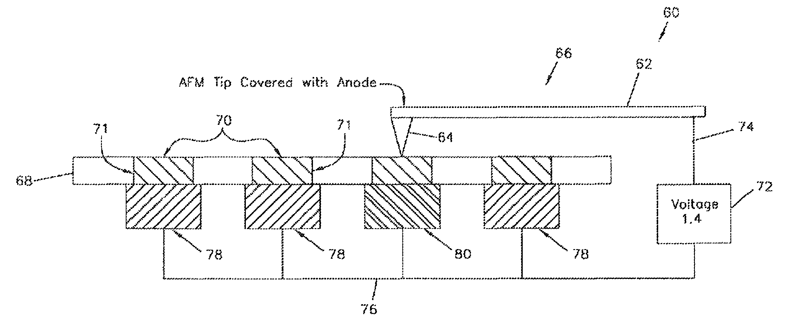
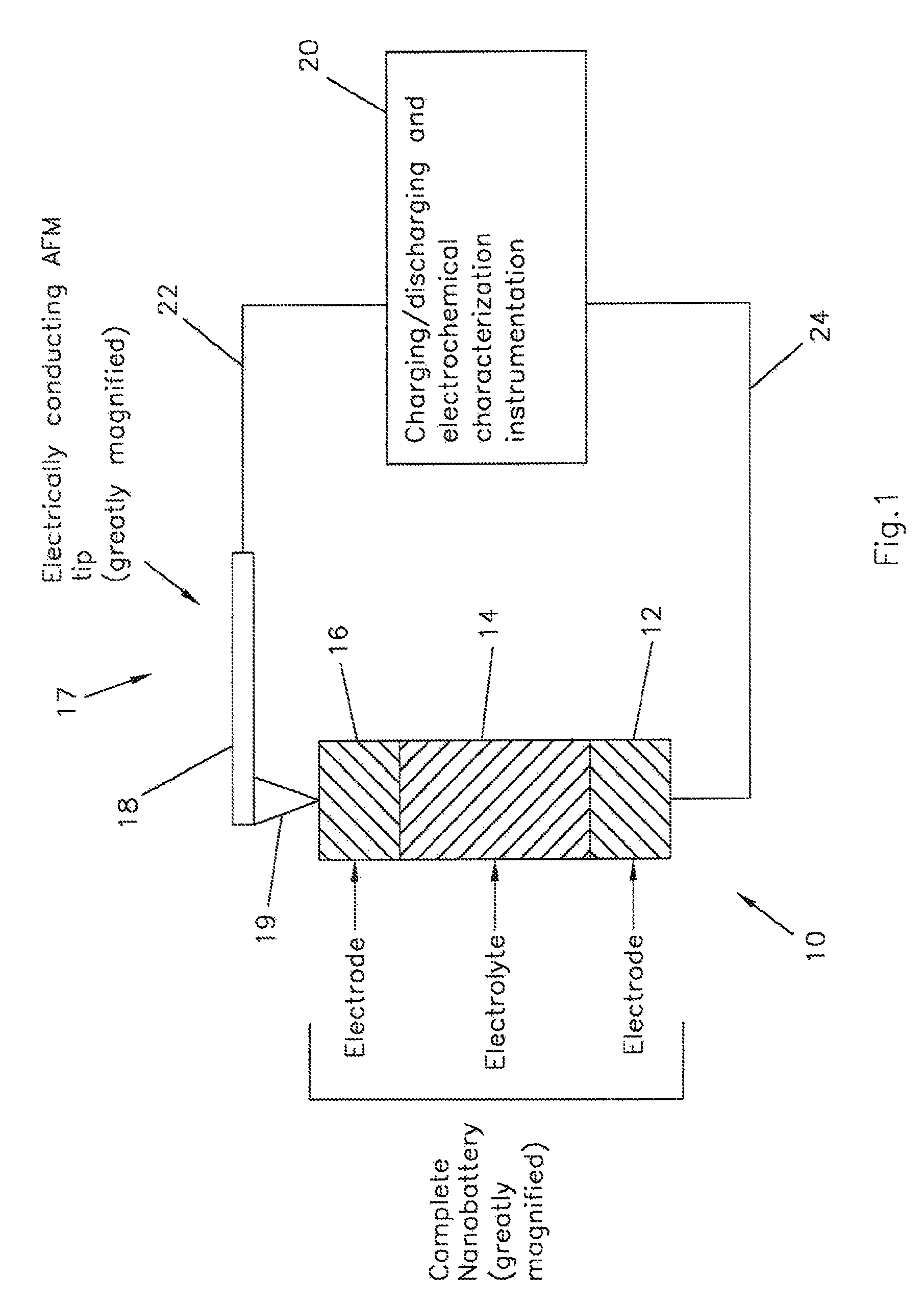
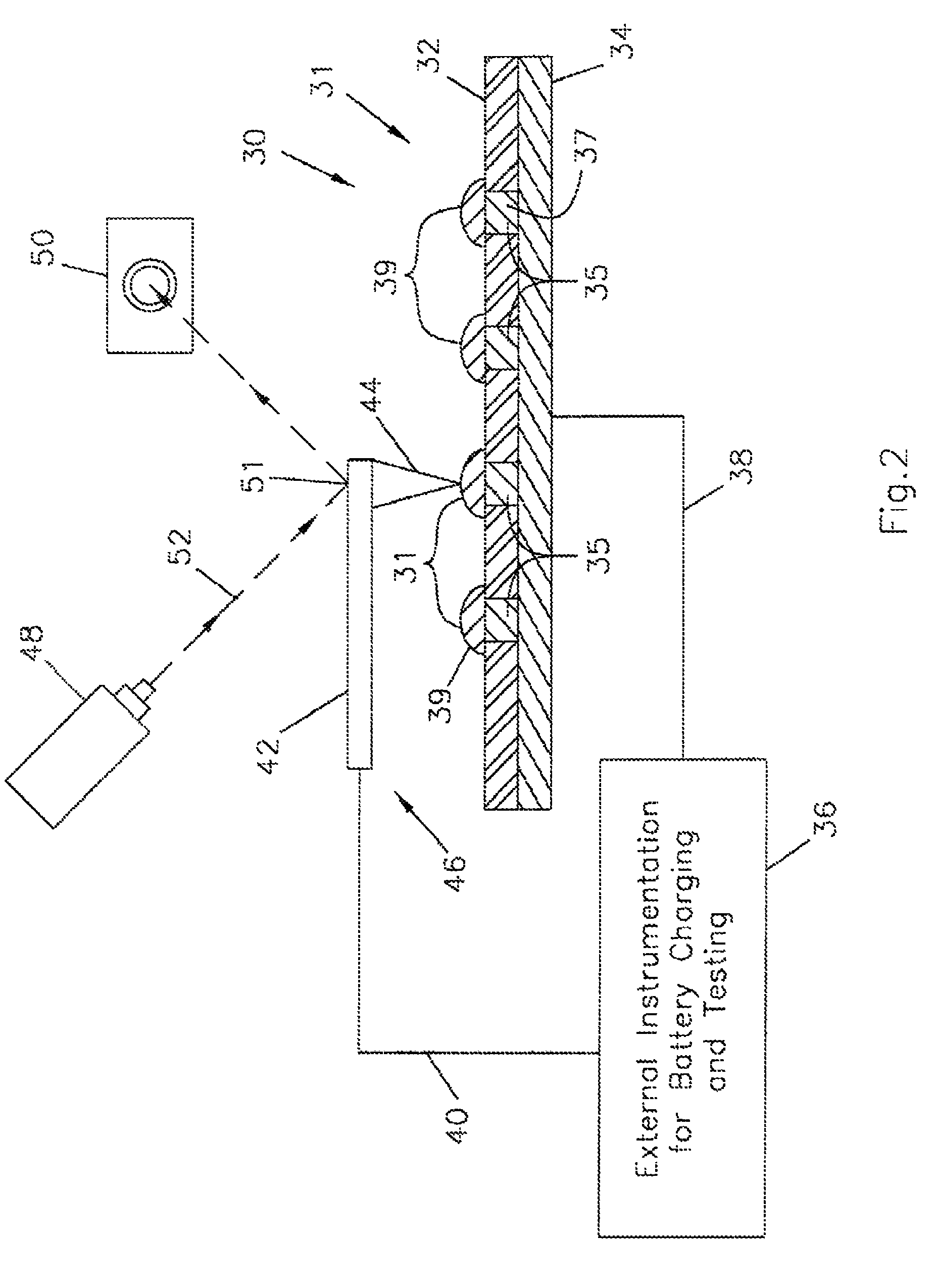
[0024]Another significant advantage of the present invention is its ability to record analog information. While known methods of data storage utilizing AFM tips may only be used for digital storage, the present invention has far broader applications. When accessed by the AFM tip or other probe, the voltage of cells having various anode / cathode combinations changes with time through the natural discharge process of the cell. An AFM tip may be programmed to first contact the cell having a various anode or cathode prior to measurements. It may be programmed to measure voltage after a certain period of time has lapsed. This allows the value of the voltage measured to vary across a continuous spectrum of time within a range of voltages. Similarly, a charged battery cell shows a decreased charge over time. The charge decreases over time such that an AFM tip may be programmed to record the charge level after a specific time period has lapsed. This allows charged readings to be taken anywhere along a continuous range of charges. Both of these methods provide for the reading of a value somewhere within a continuous spectrum. This allows storage of analog data that is not possible with storage devices that only provide for reading and writing of digital data. Those skilled in the art will appreciate that this also provides a significant advantage over the prior art.
is its ability to record analog information. While known methods of data storage utilizing AFM tips may only be used for digital storage, the present invention has far broader applications. When accessed by the AFM tip or other probe, the voltage of cells having various anode / cathode combinations changes with time through the natural discharge process of the cell. An AFM tip may be programmed to first contact the cell having a various anode or cathode prior to measurements. It may be programmed to measure voltage after a certain period of time has lapsed. This allows the value of the voltage measured to vary across a continuous spectrum of time within a range of voltages. Similarly, a charged battery cell shows a decreased charge over time. The charge decreases over time such that an AFM tip may be programmed to record the charge level after a specific time period has lapsed. This allows charged readings to be taken anywhere along a continuous range of charges. Both of these methods provide for the reading of a value somewhere within a continuous spectrum. This allows storage of analog data that is not possible with storage devices that only provide for reading and writing of digital data. Those skilled in the art will appreciate that this also provides a significant advantage over the prior art.

Problems solved by technology

One disadvantage of the IBM technique is that it is difficult and time consuming to effectively remove a single data point.
Another disadvantage is that it is difficult to effectively erase stored data completely.
The more data is stored and erased on a surface, the more convoluted the surface becomes and eventually no longer performs adequately.
Another disadvantage is that this technique may only store digital, binary data.
These planar microbatteries were 200 μm×200 μm and had capacities of 200-200 mC / cm2 at current densities of 10-20 mA / cm2 with an operating voltage of 1.5 V. A carbon-based rechargeable lithium microbattery has been contemplated, but the progress in fabricating the electrode microstructure has been slow.

Method used


Image

  • Charged arrays of micro and nanoscale electrochemical cells and batteries for computer and nanodevice memory and power supply
  • Charged arrays of micro and nanoscale electrochemical cells and batteries for computer and nanodevice memory and power supply
  • Charged arrays of micro and nanoscale electrochemical cells and batteries for computer and nanodevice memory and power supply

Examples


Embodiment Construction

[0034]The embodiments discussed herein are merely illustrative of specific manners in which to make and use the invention and are not to be interpreted as limiting the scope of the instant invention.

[0035]While the invention has been described with a certain degree of particularity, it is to be noted that many modifications may be made in the details of the invention's construction and the arrangement of its components without departing from the spirit and scope of this disclosure. It is understood that the invention is not limited to the embodiments set forth herein for purposes of exemplification.

[0036]The present invention comprises a device capable of storing information for computer applications and in microscale and nanoscale devices. Both digital and analog information may be stored. In addition, systems greater than base 2 may be designed. By using trinary or greater systems, the amount of data stored can be greatly increased. For example, three data points in a binary syste...


PUM

PropertyMeasurementUnit
output voltageaaaaaaaaaa
current densitiesaaaaaaaaaa

Abstract

A sequence or array of electrochemical cells storing both digital and analog data. Both binary code and codes having a higher base may be stored in the memory device to increase information density. Such battery arrays could also provide power for the micro or nanodevice. Devices are microscale and nanoscale in size and utilize electrically conductive atomic force microscopy tips to record and read data stored in the device.

Description

CROSS-REFERENCE TO PENDING APPLICATIONS[0001]This application is a divisional application of U.S. patent application Ser. No. 10 / 913,918, filed Aug. 6, 2004, now U.S. Pat. No. 7,704,615, which is based on U.S. Provisional Patent Application No. 60 / 493,313 filed Aug. 7, 2003 and entitled “Charged Arrays of Micro and Nanoscale Electrochemical Cells and Batteries For Computer and Nanodevice Memory and Power Supply”.STATEMENT REGARDING FEDERALLY SPONSORED RESEARCH OR DEVELOPMENT[0002]This invention was made with U.S. Government support under the Department of the Navy, Office of Naval Research contract N00014-01-1-0724 and the National Science Foundation contract EPS-0132534 awarded by the Department of Defense and the National Science Foundation. The U.S. Government has certain rights in the invention.BACKGROUND OF THE INVENTION[0003]1. Field of the Invention[0004]The present invention relates to microscale and nanoscale arrays of electrochemical cells and batteries for computer and na...

Claims


Application Information

Patent Timeline
Patent Type & Authority Patents(United States)
IPC IPC(8): H01M10/46H01M16/00
CPCG11B9/1472G11B9/1436G11B9/08B82Y10/00
Inventor TEETERS, DALELAYSON, ANTHONYDEWAN, CHRISTINA
Owner UNIVERSITY OF TULSA
Why Eureka
Eureka Blog
Learn More