Focus detection device and focus detection method based upon center position of gravity information of a pair of light fluxes

a technology of center position and gravity information, applied in the field of focus detection devices, focus detection methods and imaging apparatuses, can solve the problem of bound to contain significant errors in the defocus amount obtained from the conversion resul

Inactive Publication Date: 2011-01-04
NIKON CORP
View PDF13 Cites 30 Cited by
  • Summary
  • Abstract
  • Description
  • Claims
  • Application Information

AI Technical Summary

Problems solved by technology

For this reason, if the pair of focus detection light fluxes are actually vignetted by the aperture at the imaging optical system or a lens opening, the defocus amount obtained as the conversion result is bound to contain a significant error.

Method used


Image

  • Focus detection device and focus detection method based upon center position of gravity information of a pair of light fluxes
  • Focus detection device and focus detection method based upon center position of gravity information of a pair of light fluxes
  • Focus detection device and focus detection method based upon center position of gravity information of a pair of light fluxes

Examples


Embodiment Construction

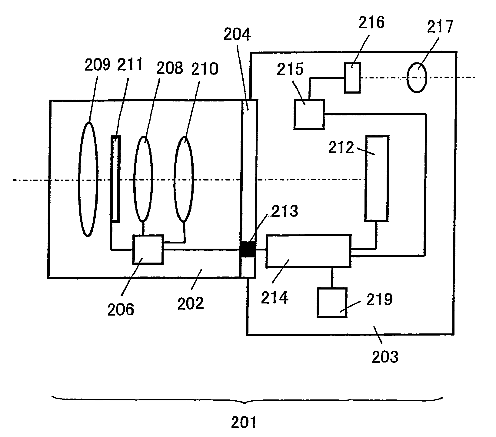
[0052]A digital still camera used in conjunction with interchangeable lenses, representing an example of an imaging apparatus equipped with the focus detection device achieved in an embodiment of the present invention is now explained. FIG. 1 is a lateral sectional view of the structure adopted in the camera in the embodiment. A digital still camera 201 achieved in the embodiment comprises an interchangeable lens 202 and a camera body 203. The interchangeable lens 202 is mounted at the camera body 203 via a mount unit 204.

[0053]The interchangeable lens 202 includes a zooming lens 208, a focusing lens 210, an aperture 211, a lens drive control device 206 and the like. The lens drive control device 206 is constituted with a microcomputer, a memory, a drive control circuit and the like (none shown). The lens drive control device 206 engages in communication with a body drive control device 214 to be detail later to transmit lens information to the body drive control device and receive ...


PUM


Abstract

A focus detection device comprises: an image shift detection unit that detects a relative shift amount of a pair of images formed by a pair of light fluxes having passed through an optical system; and a conversion unit that converts the shift amount to a defocus amount based upon dimensional information of an exit pupil corresponding to an aperture restricting light flux in the optical system and distance information of the exit pupil indicating distance to the exit pupil from a predetermined imaging plane of the optical system.

Description

INCORPORATION BY REFERENCE[0001]The disclosure of the following priority application is herein incorporated by reference: Japanese Patent Application No. 2007-109055 filed Apr. 18, 2007BACKGROUND OF THE INVENTION[0002]1. Field of the Invention[0003]The present invention relates to a focus detection device, a focus detection method and an imaging apparatus.[0004]2. Description of Related Art[0005]Japanese Laid Open Patent Application No. S57-165806 discloses a focus detection device adopting a split-pupil phase difference detection method. Such a focus detection device converts the extent of relative offset manifested by a pair of images formed with focus detection light fluxes having passed through a pair of areas at an exit pupil of an imaging optical system a defocus amount indicating the extent of defocusing manifested by the imaging optical system by using a specific conversion expression.SUMMARY OF THE INVENTION[0006]However, the conversion expression used in the focus detectio...

Claims


Application Information

Patent Timeline
Patent Type & Authority Patents(United States)
IPC IPC(8): G01B9/04G06M7/00
CPCG02B7/346H04N5/23212G03B13/36H04N23/672H04N25/704H04N25/134
Inventor KUSAKA, YOSUKE
Owner NIKON CORP
Why Eureka
Try Eureka