Method and device for calibrating a light intensity measurement device

a light intensity measurement and light intensity technology, applied in measurement devices, optical radiation measurement, instruments, etc., can solve the problems of time-consuming and labor-intensive calibration, and the operation condition of the light intensity measurement device is not always desirabl

Inactive Publication Date: 2011-01-04
NAT INST OF INFORMATION & COMM TECH
View PDF17 Cites 4 Cited by
  • Summary
  • Abstract
  • Description
  • Claims
  • Application Information

AI Technical Summary

Benefits of technology

[0009]The present invention is basically based on the following idea. A light intensity of input light is attenuated by an optical attenuator (5). Then, the intensity is measured by a light intensity measurement device (7), and the measured light intensity is stored in a control device (8). Then, a waveguide is switched to a waveguide (6) not having the optical attenuator (5) by an optical switch (3), and a signal applied to an optical intensity modulator (2) is adjusted so that the light intensity of the signal becomes equal to the measured light intensity stored in the control device (8). By repeating one or a plurality of times of the above procedure, calibration can be automatically and effectively performed.
[0014]This invention can provide a new method and a device for calibrating a light intensity measurement device which, for example, adjusts light intensity gradually.
[0015]This invention can provide a method and a device for automatically calibrating a light intensity measurement device, since the device and the method of the present invention can maintain a desirable extinction ratio by feed back control as needed.
[0016]This invention can adjust light intensity gradually. Therefore, this invention can provide a method and a device for calibrating a light intensity measurement device which can perform calibration automatically based on feed back control.

Problems solved by technology

A light intensity measurement device is not always in a desirable operational condition due to heat generated by the continuous operation of the device or changes in its operating environment.
There is also a problem that it takes time to perform calibration since a variable attenuator which requires mechanical operation is used.

Method used


Image

  • Method and device for calibrating a light intensity measurement device
  • Method and device for calibrating a light intensity measurement device
  • Method and device for calibrating a light intensity measurement device

Examples


Embodiment Construction

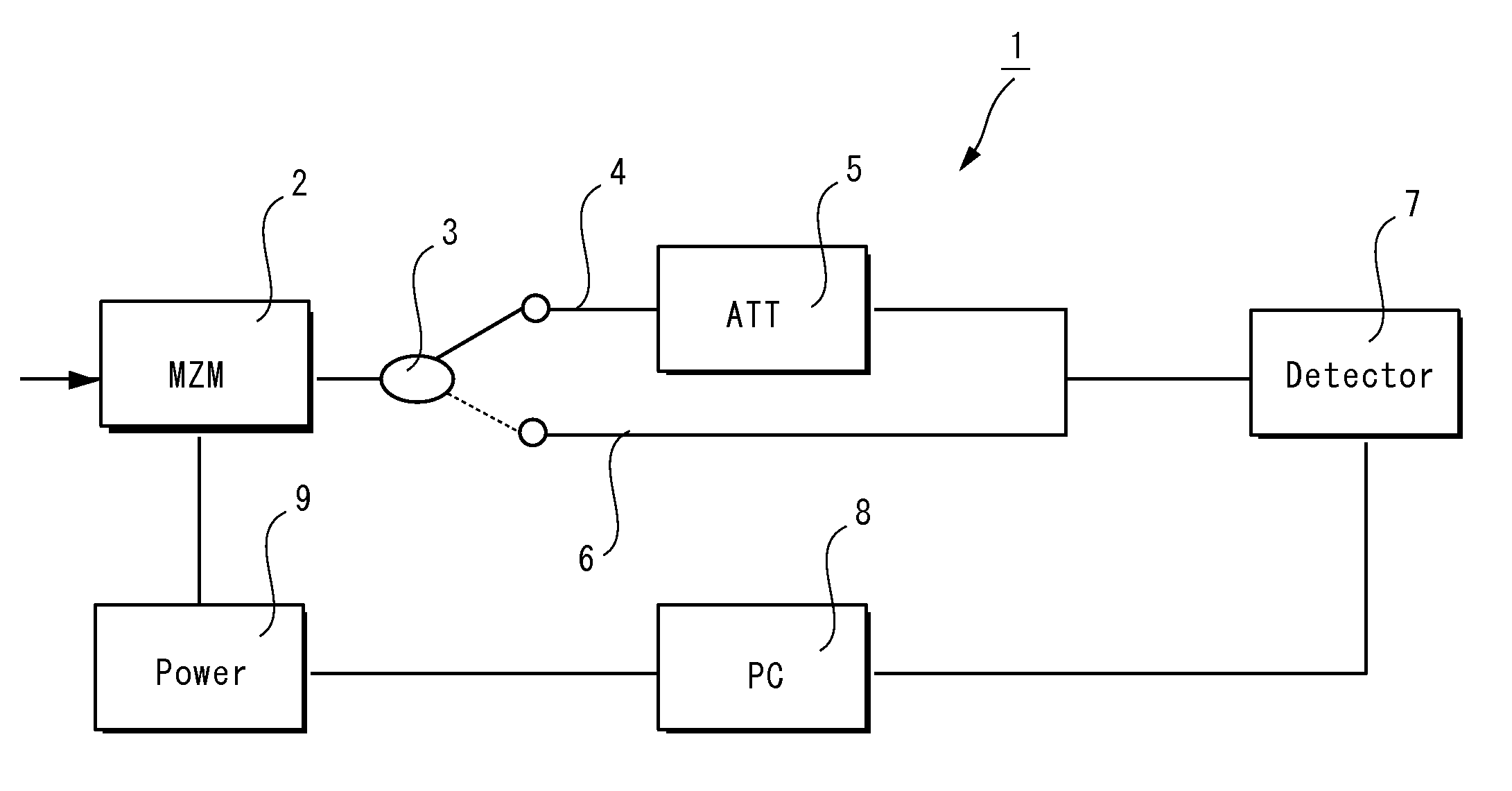
[0020]FIG. 1 is a block diagram showing a light intensity measurement device comprising the calibration device according to the first aspect of the present invention.

[0021]As shown in FIG. 1, the calibration device for a light intensity measurement device comprises: an optical switch (3) for switching output paths from an optical intensity modulator (2); a first waveguide (4) being switched by the optical switch (3); an optical attenuator (5) being provided on the first waveguide; a second waveguide (6) being switched by the optical switch (3); a light intensity measurement device (7) being connected to the first waveguide (4) and the second waveguide (6) and measuring light intensity of light propagating through the first waveguide (4) or the second waveguide (6); a control device (8) receiving the light intensity measured by the light intensity measurement device (7) and controlling a signal being applied to the optical intensity modulator (2); and a signal source (9) receiving co...


PUM


Abstract

It is an object of the present invention to provide a method and a device for automatically calibrating a light intensity measurement device. The device (1) includes an optical switch (3) for switching a route of output from an optical intensity modulator (2), an optical attenuator (5) arranged on a first waveguide (4), a second waveguide (6), a light intensity measurement device (7), a control device (8) for receiving light intensity information measured by the light intensity measurement device (7) and controlling the signal to be applied to the optical intensity modulator (2), and a signal source (9) for receiving a control signal of the control device (8) and adjusting the signal to be applied to the optical intensity modulator (2).

Description

CROSS REFERENCE TO RELATED APPLICATIONS[0001]The present disclosure is a national phase filing under 35 U.S.C. §371 of International Patent Application No. PCT / JP2006 / 323465 filed on Nov. 24, 2006, which claims priority to Japanese Patent Application No. 2005-344034 filed on Nov. 29, 2005, the disclosures of which are expressly incorporated herein by reference in its entireties.BACKGROUND OF THE INVENTION[0002]1. Field of the Invention[0003]The present invention relates to a method and a device for calibrating a light intensity measurement device. In particular, the present invention relates to a method for calibrating a light intensity measurement device by using an optical intensity modulator having ultra high extinction ratio. It also relates to a device which is configured to perform calibration operations automatically.[0004]2. Description of the Related Art[0005]A light intensity measurement device is not always in a desirable operational condition due to heat generated by the...

Claims


Application Information

Patent Timeline
Patent Type & Authority Patents(United States)
IPC IPC(8): G01B9/02
CPCG01J1/04G01J1/0418G01J1/0425G01J1/08G01J1/26G01J1/0204
Inventor KAWANISHI, TETSUYAIZUTSU, MASAYUKISAKAMOTO, TAKAHIDETSUCHIYA, MASAHIRO
Owner NAT INST OF INFORMATION & COMM TECH
Why Eureka
Try Eureka