Simulation, measurement and/or control system and method with coordinated timing

a control system and simulation technology, applied in the direction of process and machine control, instruments, analogue processes for specific applications, etc., can solve the problems of dangerous or economically infeasible, inability to perform or monitor a test, and inability to achieve real system operation

Active Publication Date: 2011-01-04
NATIONAL INSTRUMENTS
View PDF19 Cites 41 Cited by
  • Summary
  • Abstract
  • Description
  • Claims
  • Application Information

AI Technical Summary

Benefits of technology

[0023]The problems outlined above may in large part be solved by providing a system and method for coordinating timing between simulation of a system and measurement and / or control of the system. A measurement / control loop comprising a measurement / control program, a simulation program, and an execution coordination kernel is described. The simulation program may be operable to simulate any of various types of systems, including discrete-time or continuous time systems. The measurement / control program may interface with the simulation program using the same techniques as for interfacing with a real system. This may advantageously enable an operator to switch between measurement / control of a simulated system and measurement / control of a real system without needing to modify the measurement / control program. The measurement / control program may provide measurement / control logic for measuring various variables associated with the simulated system and / or controlling the simulated system.

Problems solved by technology

For example, in many situations, it may be necessary to test the measurement / control logic that will be used in an actual measurement / control loop, but it may be infeasible, impractical, or impossible to do so with the real system.
For example, it may be necessary to test whether the measurement / control logic will work properly under extreme or emergency situations in which it would be dangerous or economically infeasible to perform the test with a real system, e.g., due to the possibility of harm to the system or the environment of the system.
Also, the real system may operate under conditions that make it impossible to perform or monitor a test, as in a space flight or deep-sea dive.
Representing the forward movement of time is often one of the most difficult aspects of creating a faithful simulation of a system.
The problem may be complicated even farther when the simulation is introduced into a measurement / control loop, since the simulation must not only take into account the natural state changes as time passes, but must also coordinate with the measurement / control logic in order to respond appropriately to the control outputs produced by the measurement / control logic.
For example, if the simulation time is allowed to run ahead indefinitely between sample intervals, then the measurement / control logic may not receive an accurate reading of how variable changes occur in the simulated system.
One disadvantage is that the approach may conflict with the objectives of performing the simulation.
However, in many cases it would be very difficult to modify the existing measurement / control logic, especially if the measurement / control logic is encapsulated in an apparatus, such as an electronic control unit designed for an engine.
Another disadvantage associated with the single-program approach is that creating the simulation portion of the program and creating the measurement / control portion of the program may require substantially different skills.
However, due to the tight coupling of the two portions, the engineer who creates the simulation portion may have to understand how the measurement / control portion is constructed, and vice versa.
Tightly coupling the measurement / control logic with the simulation may inhibit this capability.
Various of the disadvantages described above, as well as additional disadvantages, also appear in the prior art when the measurement / control logic and the simulation are implemented as separate programs which communicate with each other, e.g., through a message-passing mechanism.
A further problem which may appear in the coordination approaches described above is the problem of how to ensure that the simulation program has the computed simulation variables ready to provide to the measurement / control logic when the measurement / control logic is ready for them.
Thus it may be unacceptable for the simulation to wait until simulation variables are requested by the measurement / control logic before beginning the computation of the variable values.
Another feature heretofore lacking in the prior art is the ability to easily vary the speed of the simulation, so that the simulation time runs either slower or faster than real time, if desired.

Method used


Image

  • Simulation, measurement and/or control system and method with coordinated timing
  • Simulation, measurement and/or control system and method with coordinated timing
  • Simulation, measurement and/or control system and method with coordinated timing

Examples


Embodiment Construction

FIG. 2—Exemplary System

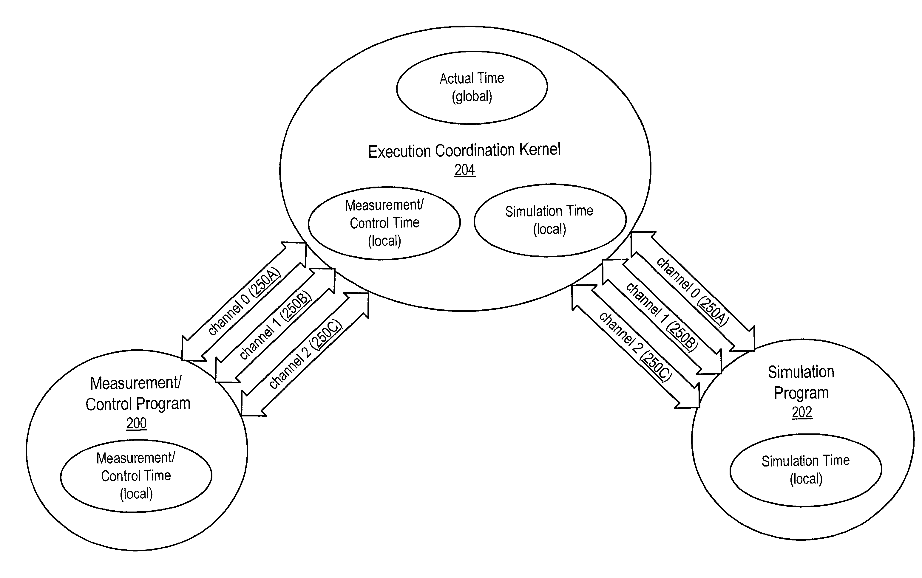
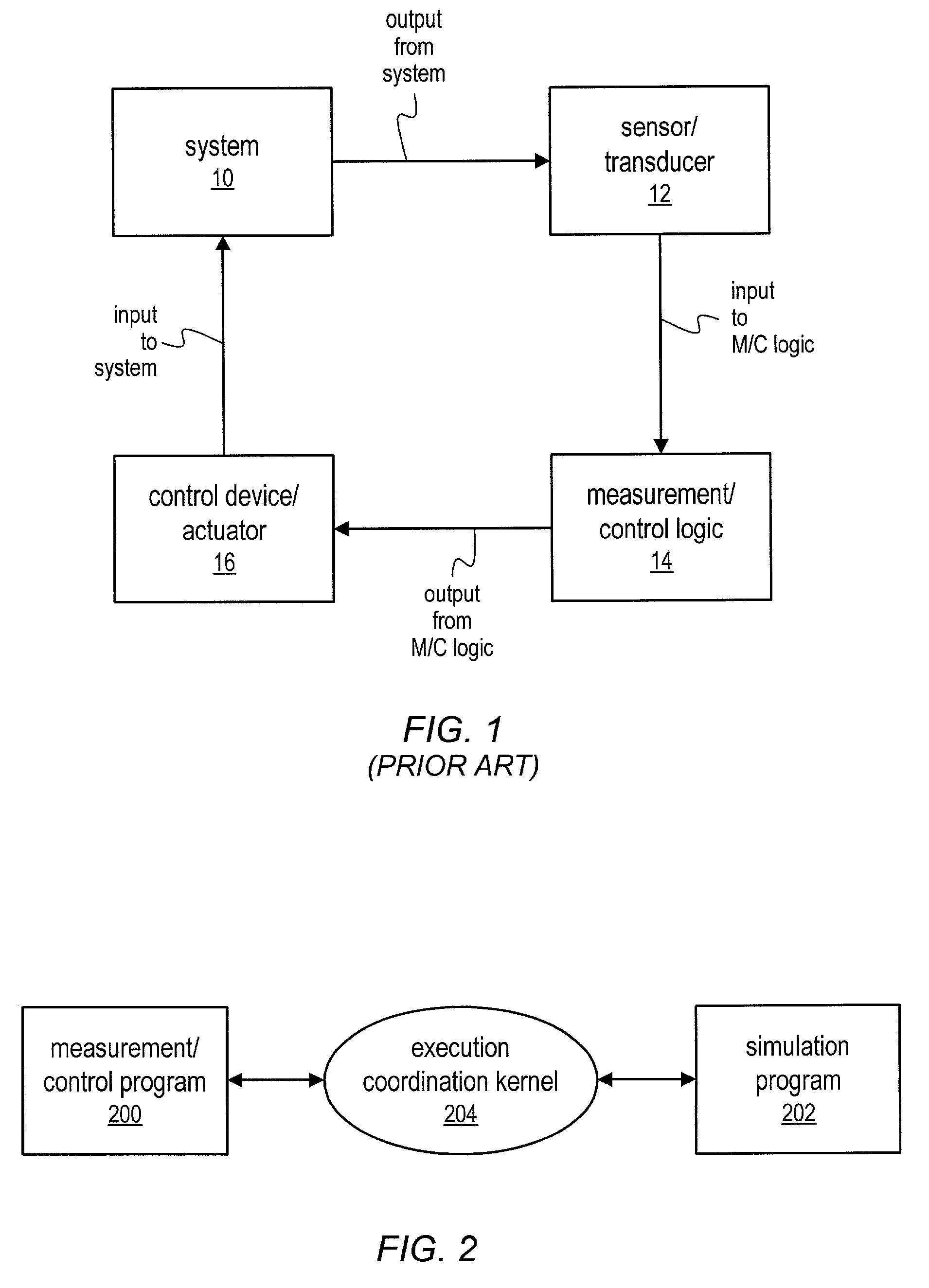
[0036]FIG. 2 is a block diagram of a system comprising a measurement / control program 200, a simulation program 202, and an execution coordination kernel 204. The system shown in FIG. 2 may enable the creation of a measurement / control loop in which the measurement / control program 200 interacts with a simulated system, i.e., the simulation program 202, instead of with a real system. The execution coordination kernel 204 is responsible for coordinating the execution and time advancement of the measurement / control and simulation programs, as described below.

[0037]As used herein, the term “measurement / control program” may refer to any of various types of programs that implement measurement / control logic for a measurement / control loop, such as shown in FIG. 1. A measurement / control program 200 may perform any combination of measurement and / or control of a system or a simulated system, as well as other types of tasks. The program 200 may run in any of various types o...


PUM


Abstract

A system and method for coordinating timing between simulation of a system and measurement and/or control of the system. A measurement/control loop comprising a measurement/control program, a simulation program, and an execution coordination kernel is described. The simulation program may be operable to simulate any of various types of systems. The measurement/control program may provide measurement/control logic for measuring various variables associated with the simulated system. The execution coordination kernel is responsible for coordinating the execution and time advancement of the measurement/control and simulation programs. The execution coordination kernel may be operable to intercept I/O calls produced by the measurement/control program and the simulation program. If the execution coordination kernel determines that the system is in simulation mode, the calls may be routed to software routines instead of to the I/O hardware.

Description

PRIORITY CLAIM[0001]This application claims benefit of priority of U.S. provisional application Serial No. 60 / 262,831 titled “Simulation, Measurement and / or Control System and Method with Coordinated Timing” filed Jan. 19, 2001, whose inventors are Jeffrey Kodosky and Jack MacCrisken.FIELD OF THE INVENTION[0002]The present invention relates to the fields of simulation and measurement and / or control systems, and more particularly to a system and method for coordinating timing between simulation of a system and measurement and / or control of the system.DESCRIPTION OF THE RELATED ART[0003]The use of measurement / control loops for measuring and / or controlling a wide variety of systems is constantly increasing. FIG. 1 (prior art) illustrates an example of a simple measurement / control loop. The system 10 shown in FIG. 1 may be any of various types of apparatuses, processes, or conditions. The system 10 may include any of various types of physical, mechanical, electrical, chemical, or thermo...

Claims


Application Information

Patent Timeline
Patent Type & Authority Patents(United States)
IPC IPC(8): G06F17/50G06F9/44G06G7/62G05B17/02
CPCG05B17/02
Inventor KODOSKY, JEFFREY L.MACCRISKEN, JACK E.
Owner NATIONAL INSTRUMENTS
Why Eureka
Try Eureka