Automated remote carriage for tightening generator wedges

a generator wedge and remote carriage technology, applied in the field of remote-controlled unmanned robotic vehicles, can solve the problems of stator wedges holding the stator coils loose, experienced very high forces, and stator wedges destroying stators, etc., and achieve the effect of increasing the width of the wedg

Active Publication Date: 2011-01-11
SIEMENS ENERGY INC
View PDF13 Cites 31 Cited by
  • Summary
  • Abstract
  • Description
  • Claims
  • Application Information

AI Technical Summary

Benefits of technology

[0013]In still another embodiment, the first telescoping member engages a hole in the insert to the wedge, and the second telescoping member engages a first end of the main body of the wedge that is opposite to a second end of the main body of the wedge into which the insert enters. Preferably, the wedge has an inclined, tapered surface where the insert contacts the main body of the wedge and desirably the main body of the wedge has a mating inclined, tapered surface where the insert contacts the main body of the wedge. A hydraulic or pneumatic cylinder and piston connected to either the first or second telescoping member moves either the first or second telescoping member in the one direction to increase the width of the wedge. Preferably, the other of the telescoping members is held in a stationary position while the insert is moved into the main body of the wedge. Desirably, the wedge insert has a hole that is engaged by either the first or second telescoping member and the main body of the wedge has a slot through which the hole in the insert can be engaged. When fully extended, the extended length of the telescoping member and width of the frame exceeds the clearance distance between the stator and rotor of the dynamoelectric machine.

Problems solved by technology

They therefore experience very high forces tending to displace them within the slots.
If steps are not taken to prevent such an occurrence, the forces acting on the conductors are sufficient to displace them in the slots and to damage or destroy the stator.
With years of normal operation of such dynamoelectric machines, the stator wedges holding the stator coils can become loose.
An undetected loose wedge condition can result in excessive vibration of the coils and eventually lead to a catastrophic failure of the machine.
This is a time-consuming and expensive process.

Method used


Image

  • Automated remote carriage for tightening generator wedges
  • Automated remote carriage for tightening generator wedges
  • Automated remote carriage for tightening generator wedges

Examples


Embodiment Construction

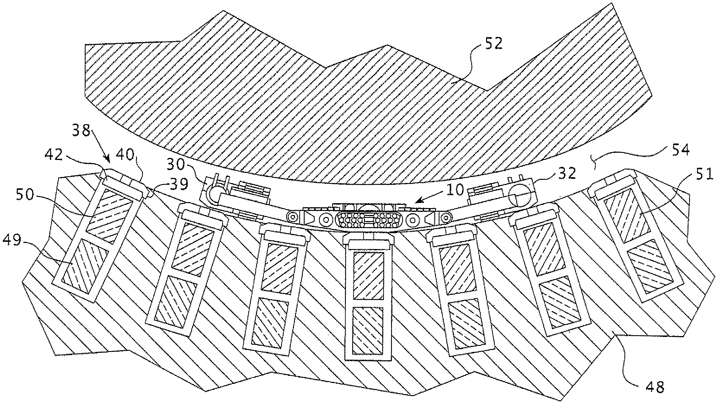
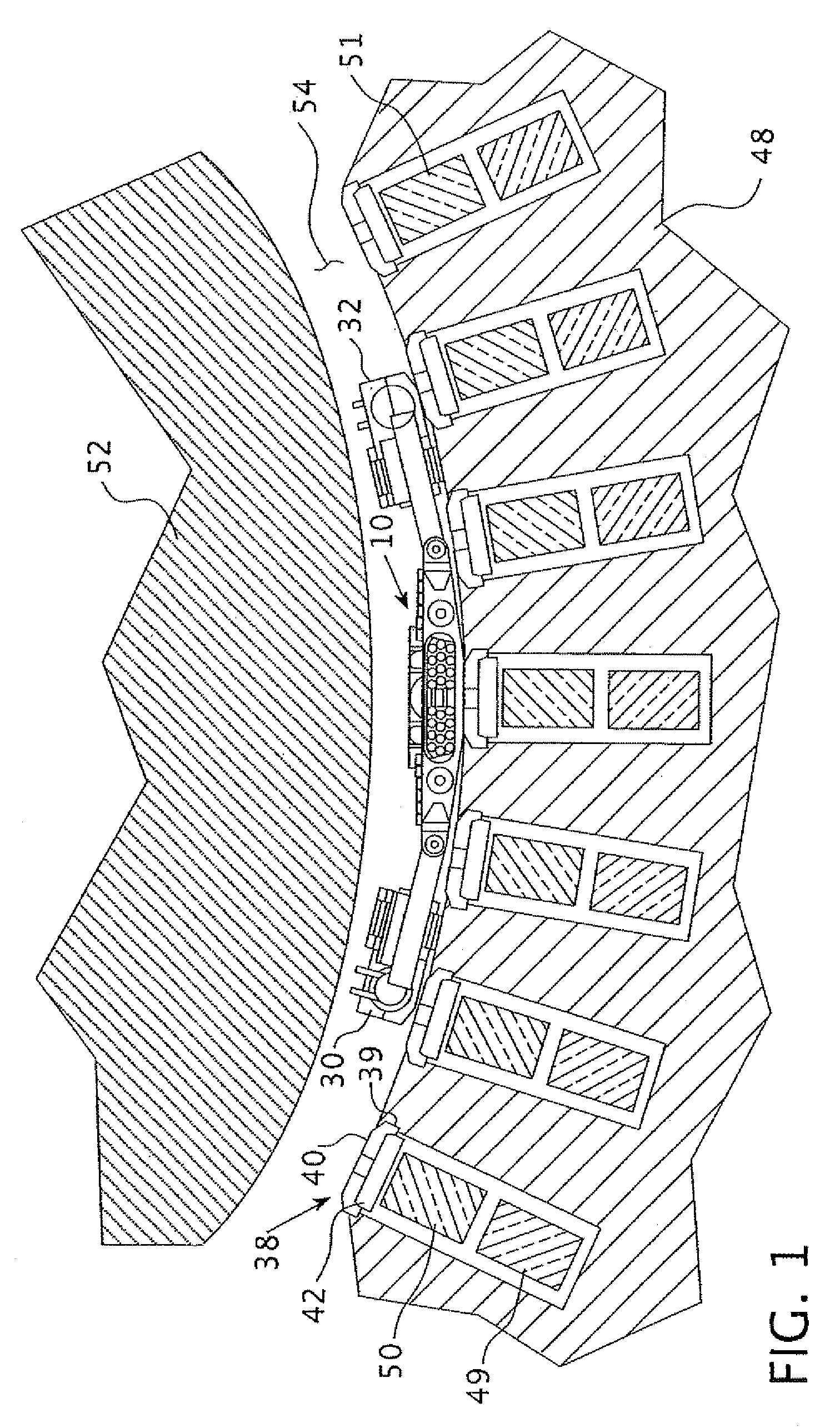
[0024]FIG. 1 shows a partial cross-section of a generator rotor 52 and stator 48 with coil slots 51. A top coil 50 and bottom coil 49 is firmly situated in each of the coil slots 51 and, as will be described more fully hereafter, is held firmly in place by the wedge 38. The wedge 38 includes a main body 40 and insert 42 which cooperate together to firmly hold the wedge 38 within the dovetail 39 of the coil slot 51. The remote controlled dynamoelectric machine maintenance vehicle 10 of this invention is shown resting on the surface of the generator stator 48, flanked by its motorized track drive assemblies 30 and 32 within the air gap 54 between the generator stator 52 and the generator rotor 48. The maintenance vehicle of this invention 10 is shown centered over the main body 40 of a wedge 38 in position to tighten the wedge, as will explained more fully hereafter.

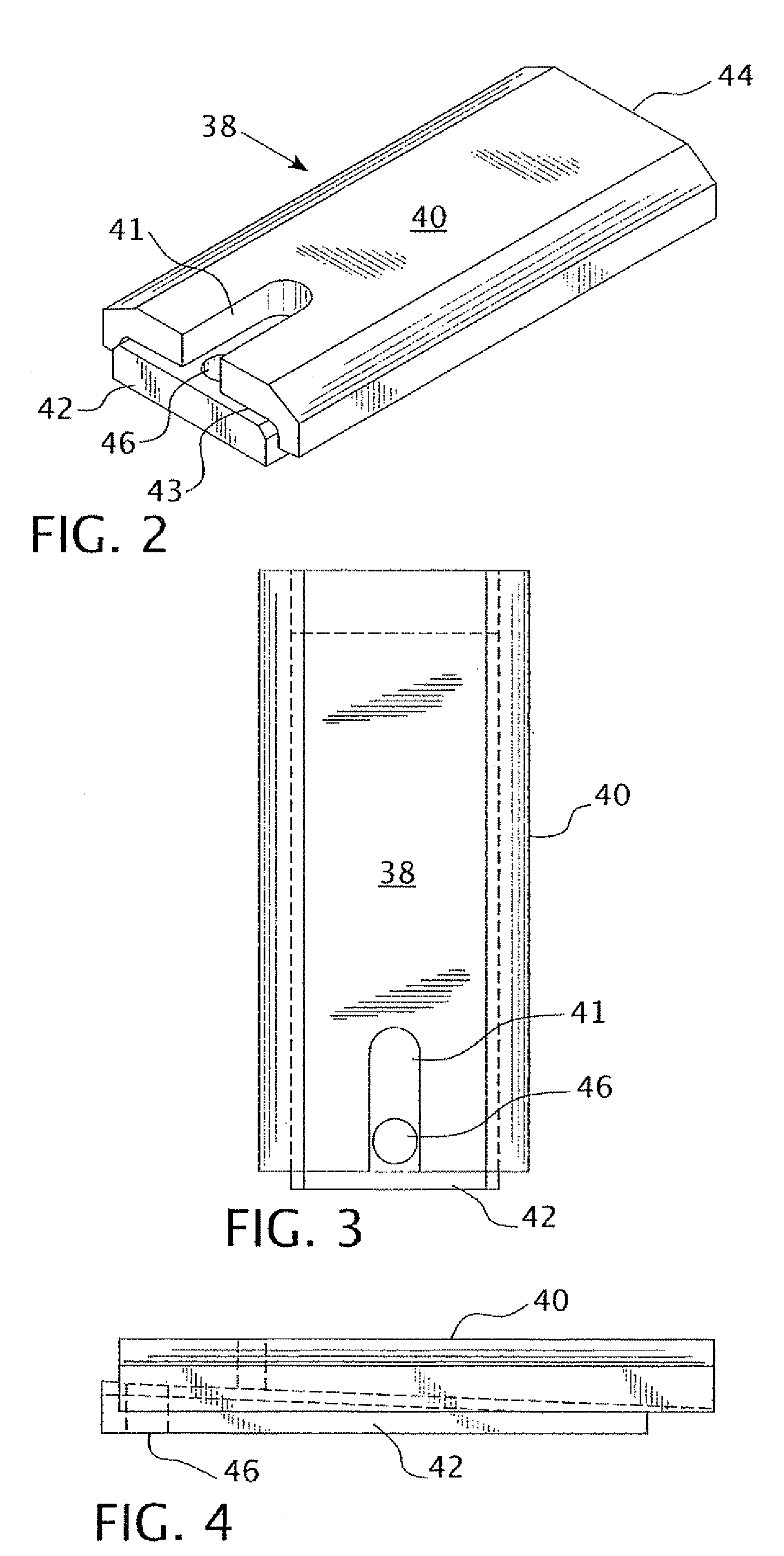
[0025]The wedge 38 is more fully illustrated in FIGS. 2, 3 and 4. The peripheral cross-section of the main body 40 of th...


PUM

PropertyMeasurementUnit
frequencyaaaaaaaaaa
magnetic adhesionaaaaaaaaaa
motive forceaaaaaaaaaa

Abstract

A remote-controlled dynamoelectric machine maintenance vehicle that can fit and travel within the air gap between a stator and rotor of a dynamoelectric machine. The maintenance vehicle has an effectuator that can remotely attach to an adjustable wedge within a coil slot of the stator and tighten the wedge in position and then move on to repeat the process until all the wedges on the stator are secured.

Description

BACKGROUND OF THE INVENTION[0001]1. Field of the Invention[0002]The present invention relates to remote-controlled unmanned robotic vehicles. More specifically, the present invention relates to remote-controlled vehicles capable of movement within the air gap between a rotor and stator of a dynamoelectric machine to tighten wedges in the machine's stator slots.[0003]2. Description of Related Art[0004]In dynamoelectric machines and, particularly in the stators of large dynamoelectric machines, it is conventional to build up an annular magnetic mass by stacking thin laminations of magnetic material on key bars. The laminations conventionally include slot-shaped openings therein which are aligned in the stacking process with corresponding openings in all other laminations to form a set of parallel slots in the inner surface of the annular magnetic mass. One or more conductors are placed in each slot to receive the generated electricity if the dynamoelectric machine is a generator or, t...

Claims


Application Information

Patent Timeline
Patent Type & Authority Patents(United States)
IPC IPC(8): B62D63/02
CPCH02K15/0018Y10T29/53143
Inventor MOORE, CHARLES C.FISCHER, MARK W.BAUER, JAMES A.SPRUDA, WALDEMARFROEDE, OLAF
Owner SIEMENS ENERGY INC
Why Eureka
Try Eureka