Roller actuating device for machines used for processing metal products

a technology of actuating device and metal product, which is applied in the direction of roller-way, transportation and packaging, manufacturing tools, etc., can solve the problems of major maintenance difficulties and inability to transmit high torque values, and achieve the effect of transmitting higher torqu

Inactive Publication Date: 2011-01-11
DANIELI & C OFF MEC SPA
View PDF26 Cites 0 Cited by
  • Summary
  • Abstract
  • Description
  • Claims
  • Application Information

AI Technical Summary

Benefits of technology

[0012]An objective of the present invention is to achieve an innovative roller actuating device for machines—e.g. flattening machines used for processing strips or sheet metal, or other similar products—extremely functional and capable of transmitting higher torques.
[0013]Another objective is to provide a much more compact roller actuating device than the one used in other known devices, thereby considerably reducing the space occupied by the whole machine throughout the whole production line and, at the same time, minimizing implementation costs.
[0021]This solution makes it possible to transmit high torque values by using the toothed adapters between the distributor and the rollers, said adapters being much more compact than the gimbal adapters, and to have a compact transmission system by using planetary reduction gears instead of large flat reduction gears in case considerable reduction ratios are required. If small reduction ratios are required, it is possible, as an alternative, to use flat reduction gears.
[0022]The device advantageously includes a finger arrangement of the distributor gears which makes it possible to optimize the spaces and move the shaft motion output axes closer in order to reduce the operating angles of the toothed adapters, preferably between 0 and 2°.

Problems solved by technology

However, all these devices or roller actuating systems have various disadvantages, which basically:do not allow the transmission of high torque values because of the use of cardan shafts, such as gimbal adapters;include considerable overall dimensions, especially where the motion transmission gears are located, particularly the motors, which are quite large;involve major maintenance difficulties in case the inspection and removal of some components (e.g. adapters or internal gears of the reduction unit) is required.

Method used


Image

  • Roller actuating device for machines used for processing metal products
  • Roller actuating device for machines used for processing metal products
  • Roller actuating device for machines used for processing metal products

Examples


Embodiment Construction

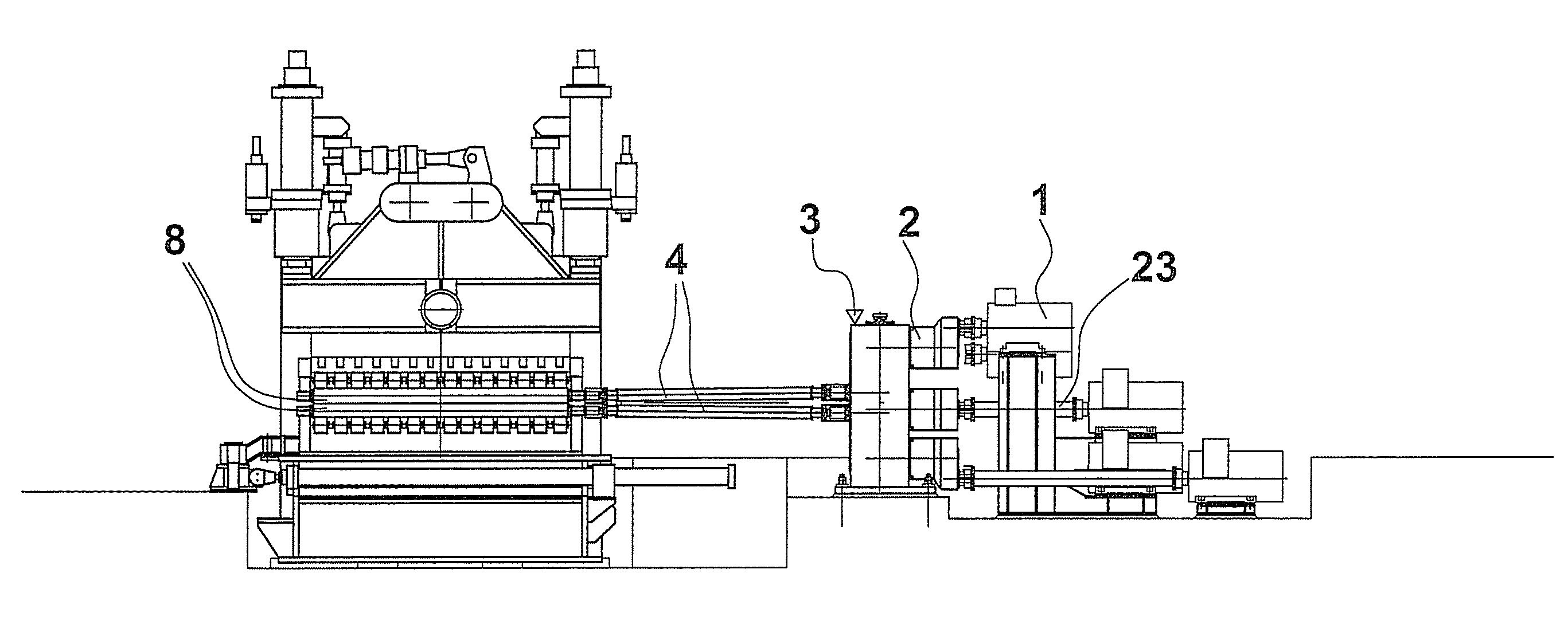
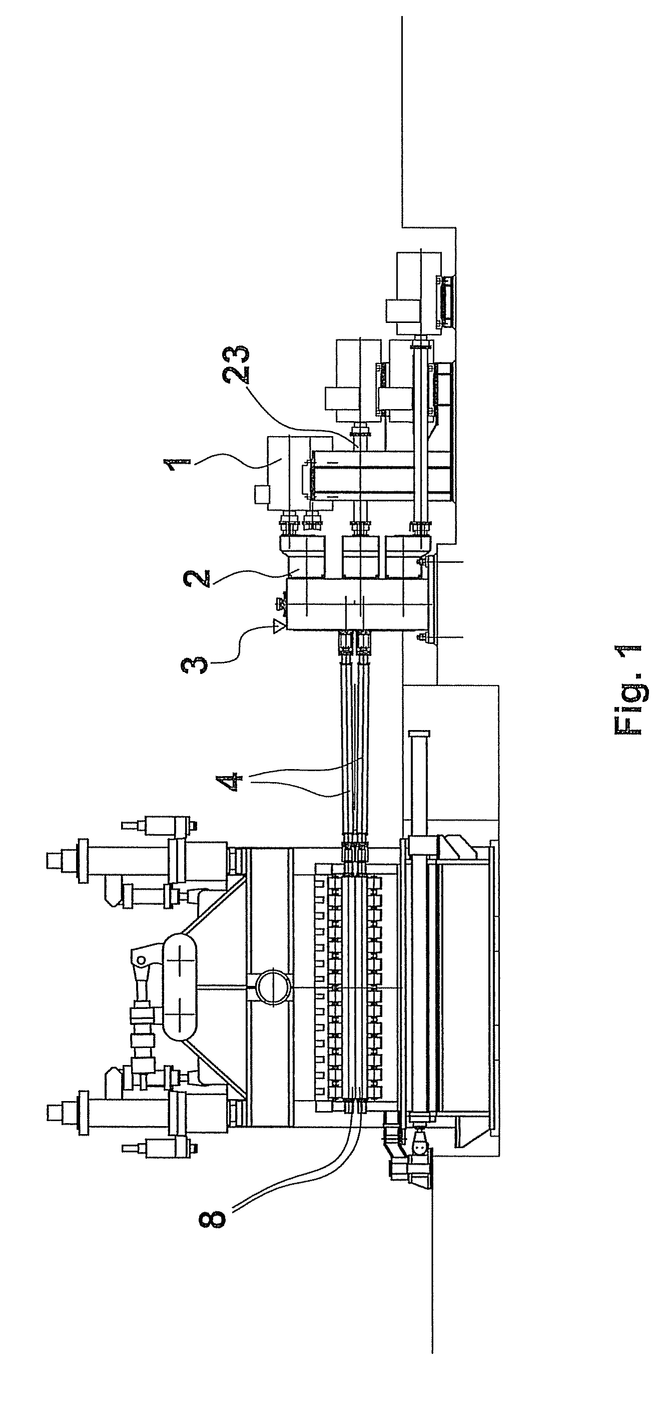
[0032]The Figures show a roller actuating device 8 of a flattening machine used for processing strips or other similar metal products. Each roller 8, called flattening roller, is individually operated by means of the following components:[0033]an electric motor 1;[0034]a reduction gear 2 with a train of crown wheels with cylindrical pre-reduction;[0035]a three gear distribution 3′, with a center spacer idle wheel 12;[0036]a toothed adapter 4.

[0037]All distributions 3′ with three or more gears, one for each roller 8, make up the distributor 3.

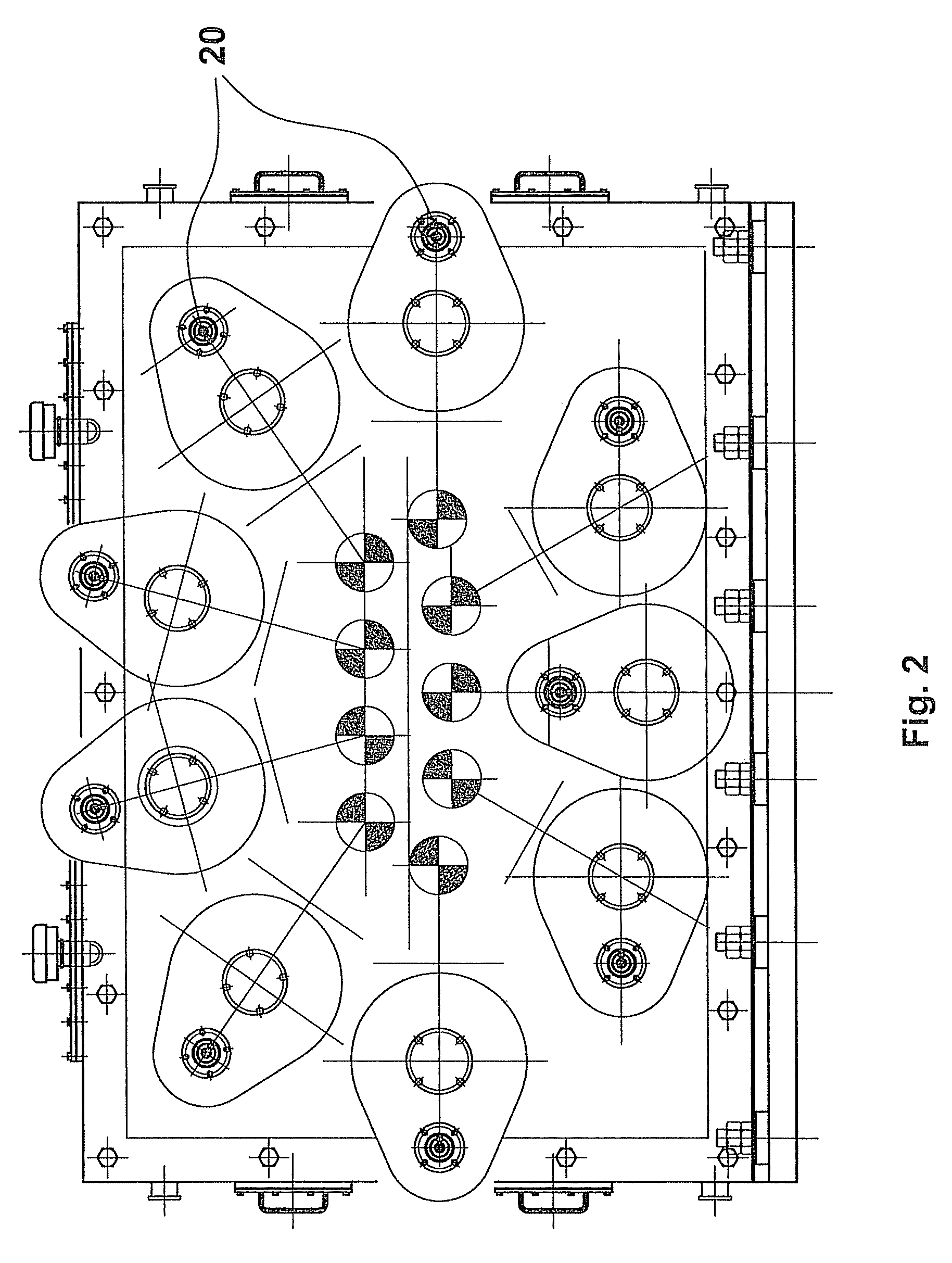
[0038]A toothed gear mating with, for instance, the pinion 21 and the sprocket 22, which make up a first reduction gear unit, shall be required between the reduction gears 2 with a train of crown wheels and their corresponding motors 1. Each pinion 21 is integral with an input shaft 20 directly connected to its motor.

[0039]Since in this zone there are low torque values, it could be possible to use either gimbal adapters or toothed joints 23 to c...


PUM

PropertyMeasurementUnit
operating anglesaaaaaaaaaa
tensionaaaaaaaaaa

Abstract

Roller actuating device for flattening machines used for metal products in the shape of sheet metal, strips or the like, also used with similar machines for other applications, comprising a device for transmitting motion to driven rolls (8), extremely functional and capable of transmitting higher torques as well as their independent control. Such device overcomes the frequent problems concerning the space available for installing gimbal adapters. This can be achieved by using adapters (4) provided with teeth which, with the same flange diameter, are able to provide higher torques, and in any case, can be used in any applications in which it is necessary to have reduced operating angles of the adapters.

Description

FIELD OF INVENTION[0001]The present invention relates to a roller actuating device for machines—in particular, for flattening machines known as “levelers”—used for processing metal products such as sheet metal, strips or other similar metal products, comprising devices for transmitting motion to the operating rollers. This device can be used for any application in which the pitch between the driven rollers is so reduced that it may affect the use of articulated transmission members.STATE OF THE ART[0002]Different devices for operating the rollers of machines used for processing metal products are known, mainly flattening machines or “levelers”.[0003]A first embodiment of a roller actuating mechanism of a flattening machine is described in the document DE3501871 in which the flattening rollers are supported by supporting rollers, each of which is individually controlled by its motor by means of its own gear unit. The flattening rollers or supporting rollers are connected with cardan ...

Claims


Application Information

Patent Timeline
Patent Type & Authority Patents(United States)
IPC IPC(8): B65G13/06
CPCB21D1/02
Inventor VIGANO', CLAUDIOSANDRIN, LUCA
Owner DANIELI & C OFF MEC SPA
Why Eureka
Try Eureka