
Braking system for vehicles, in particular utility vehicles, comprising at least two separate electronic braking control circuits

a technology for braking systems and utility vehicles, applied in brake control systems, brake systems, vibration dampers, etc., can solve problems such as faults, and achieve the effect of increasing fail-safety or reliability

Active Publication Date: 2011-01-11
KNORR-BREMSE SYST FUER NUTZFAHRZEUGE GMBH
View PDF24 Cites 29 Cited by
  • Summary
  • Abstract
  • Description
  • Claims
  • Application Information

AI Technical Summary

Benefits of technology

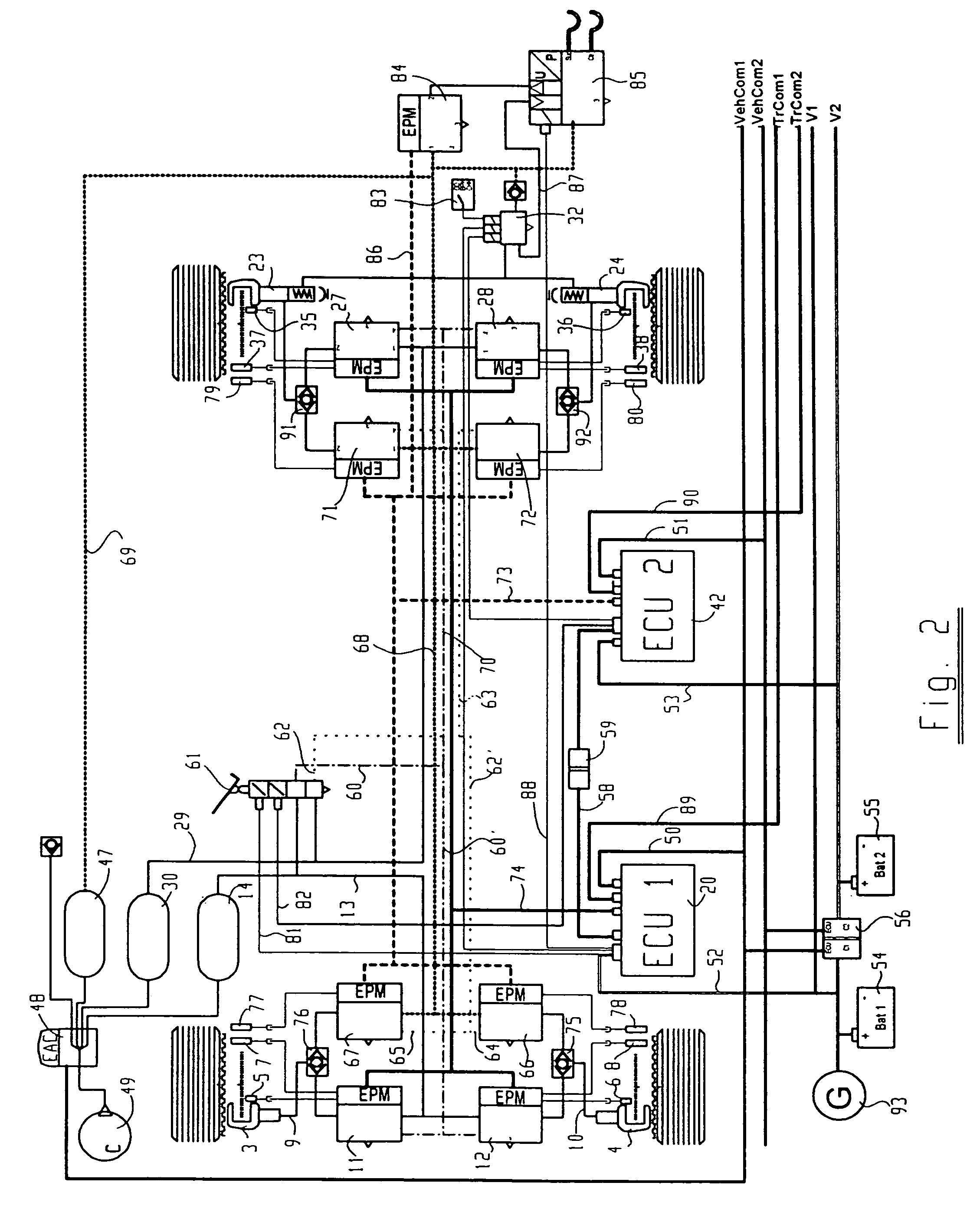
The present invention provides a braking system that can be activated electrically, has increased fail-safe or reliability, and can carry out higher functions such as ABS, ASR, EBS etc. The braking system comprises at least two or more electrical or electronic braking control systems, individual brake actuators or groups of brake actuators being assigned to different braking control systems, to be precise in such a manner that there are brake actuators which can be activated by a plurality of braking control systems. The individual braking control systems may be isolated from one another in such a manner that a fault in one of the braking control systems does not affect the other braking control system(s). The braking system may be easily changed over from the current electropneumatic brake components to purely electrically controlled components. The brake circuits may be divided between individual vehicle brakes in different ways. The first brake circuit has the function of a service brake circuit, and the second brake circuit assumes the function of the service brake circuit in case of failure. Each brake circuit is respectively provided with its own electronic control unit, which can communicate with one another via a communications line in such a manner that they are DC-isolated. The braking system may be DC-isolated from other systems in the vehicle.

Problems solved by technology

A fault is then deemed to be present when the two control units determine different control signals from the same sensor input signals.

Method used


Image

  • Braking system for vehicles, in particular utility vehicles, comprising at least two separate electronic braking control circuits
  • Braking system for vehicles, in particular utility vehicles, comprising at least two separate electronic braking control circuits
  • Braking system for vehicles, in particular utility vehicles, comprising at least two separate electronic braking control circuits

Examples


Embodiment Construction

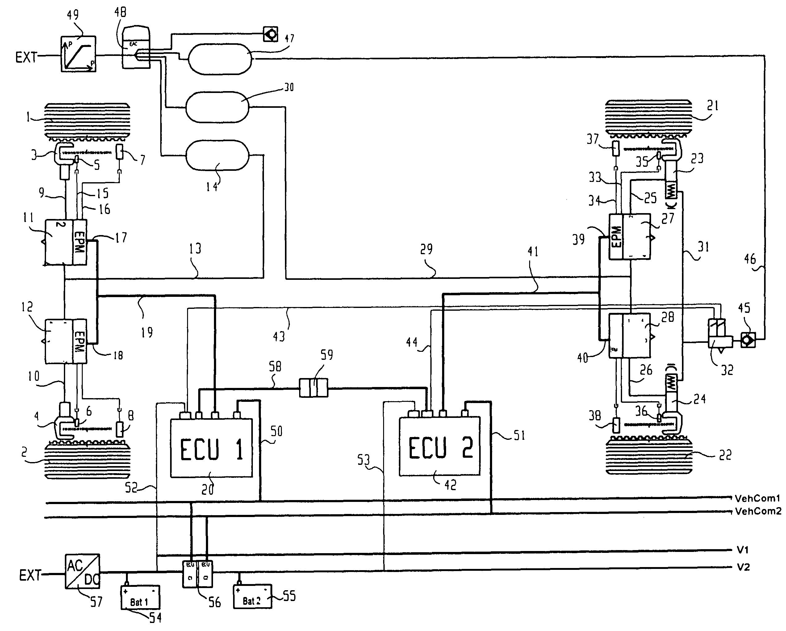
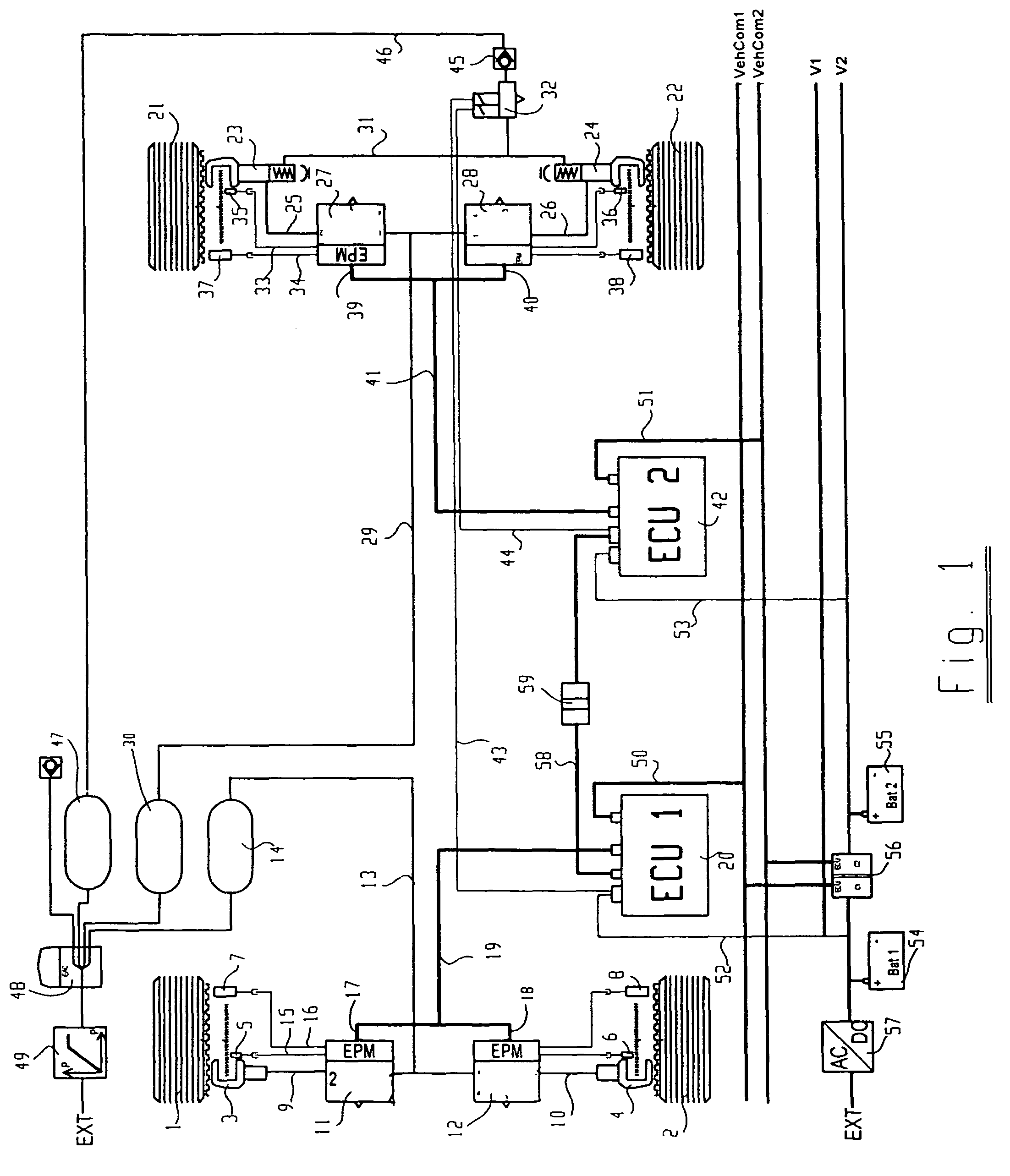
[0028]FIG. 1 shows a schematic illustration of an electropneumatic vehicle braking system. Front wheels 1, 2 are each assigned a brake cylinder 3, 4, a brake lining wear sensor 5, 6 and a wheel speed sensor 7, 8. Brake pressure is applied to the brake cylinders 3, 4 by associated electropneumatic pressure regulation modules 11, 12 (EPM) via pneumatic lines 9, 10. The two pressure regulation modules 11, 12 are connected in this case, via a common supply line 13, to a first compressed-air store 14 which is assigned to the front axle. The brake lining wear sensors 5, 6 and the wheel speed sensors 7, 8 are each connected to signal inputs of the pressure regulation modules 11, 12 via electrical lines 15, 16. The pressure regulation modules 11, 12 also each have an electrical control input 17, 18, the latter being connected to a first electronic control unit 20 via electrical lines 19 which are shown only schematically in this case. The electronic control unit 20 thus controls the braking...


PUM


Abstract

A braking system for vehicles, including at least one first brake circuit, and at least one second brake circuit, in which the at least one first brake circuit and the at least one second brake circuit each have an electrical control circuit, which respectively has an electronic control unit and its own power supply device, and brake actuating devices which are activatable by the electronic control units, at least one of the brake actuating devices being activatable by more than one of the electronic control units, in which the brake circuits are electrically activatable via a foot brake valve, and the foot brake valve has two electrical braking transmitter devices which are each connected to the electronic control units so that they are DC-isolated.

Description

RELATED APPLICATION INFORMATION[0001]The present application claims the benefit of and was filed as PCT / EP2004 / 004810 on May 6, 2004 which claims priority to German patent application no. 103 20 608.6, which was filed in the German patent office on May 8, 2003. Both applications (including the English translation of PCT / EP2004 / 004810 filed herewith) are all hereby incorporated by reference in their entirety.FIELD OF THE INVENTION[0002]The present invention relates to a braking system for vehicles.BACKGROUND INFORMATION[0003]DE 199 04 721 A1 refers to an electromechanically actuated vehicle braking system which has electrical braking control circuits, namely one for the brakes on the front axle and one for the brakes on the rear axle. The two control circuits each have their own power supply and their own electronic control unit, which are electrically connected to a brake pedal. The two control units operate independently of one another but can communicate with one another and can t...

Claims


Application Information

Patent Timeline
Patent Type & Authority Patents(United States)
IPC IPC(8): B60T13/00B60T8/88B60T13/66
CPCB60T13/66B60T2270/402B60T8/321
Inventor GERUM, EDUARDBROCH, WALTERCSAK, BENCEGIANONE, LASZLO
Owner KNORR-BREMSE SYST FUER NUTZFAHRZEUGE GMBH
Learn More