Liner for a gas turbine engine casing

a gas turbine engine and liner technology, applied in the direction of liquid fuel engines, machines/engines, efficient propulsion technologies, etc., can solve the problems of reducing the effectiveness of absorbing noise, or attenuating sound, steps and gaps affecting the aerodynamic flow over the acoustic liner, and interfere with the ability of the fan casing to contain a detached fan blad

Active Publication Date: 2011-01-11
ROLLS ROYCE PLC
View PDF20 Cites 50 Cited by
  • Summary
  • Abstract
  • Description
  • Claims
  • Application Information

AI Technical Summary

Problems solved by technology

However, the fasteners extend radially through reinforced regions of the acoustic liner and these reinforced regions reduce the acoustic liner face area, which reduces the effectiveness to absorb noise, or attenuate sound, and the fasteners produce steps and gaps which affect the aerodynamic flow over the acoustic liner.
The use of adhesive bonding may be used to secure the acoustic liner to the fan casing, but subsequent replacement would be difficult and any damage to the acoustic liner would require repair using filler and this would also interfere with the ability of the fan casing to contain a detached fan blade.
However, if the fan blade track liner becomes damaged subsequent removal and replacement is difficult and time consuming.
Furthermore, during the removal of a damaged fan blade track liner there is a risk of damaging the fan casing and reducing the ability of the fan casing to contain a detached fan blade.
It is possible to increase the thickness of the fan casing to allow for possible fan casing damage, however this adds weight to the gas turbine engine.

Method used


Image

  • Liner for a gas turbine engine casing
  • Liner for a gas turbine engine casing
  • Liner for a gas turbine engine casing

Examples


Embodiment Construction

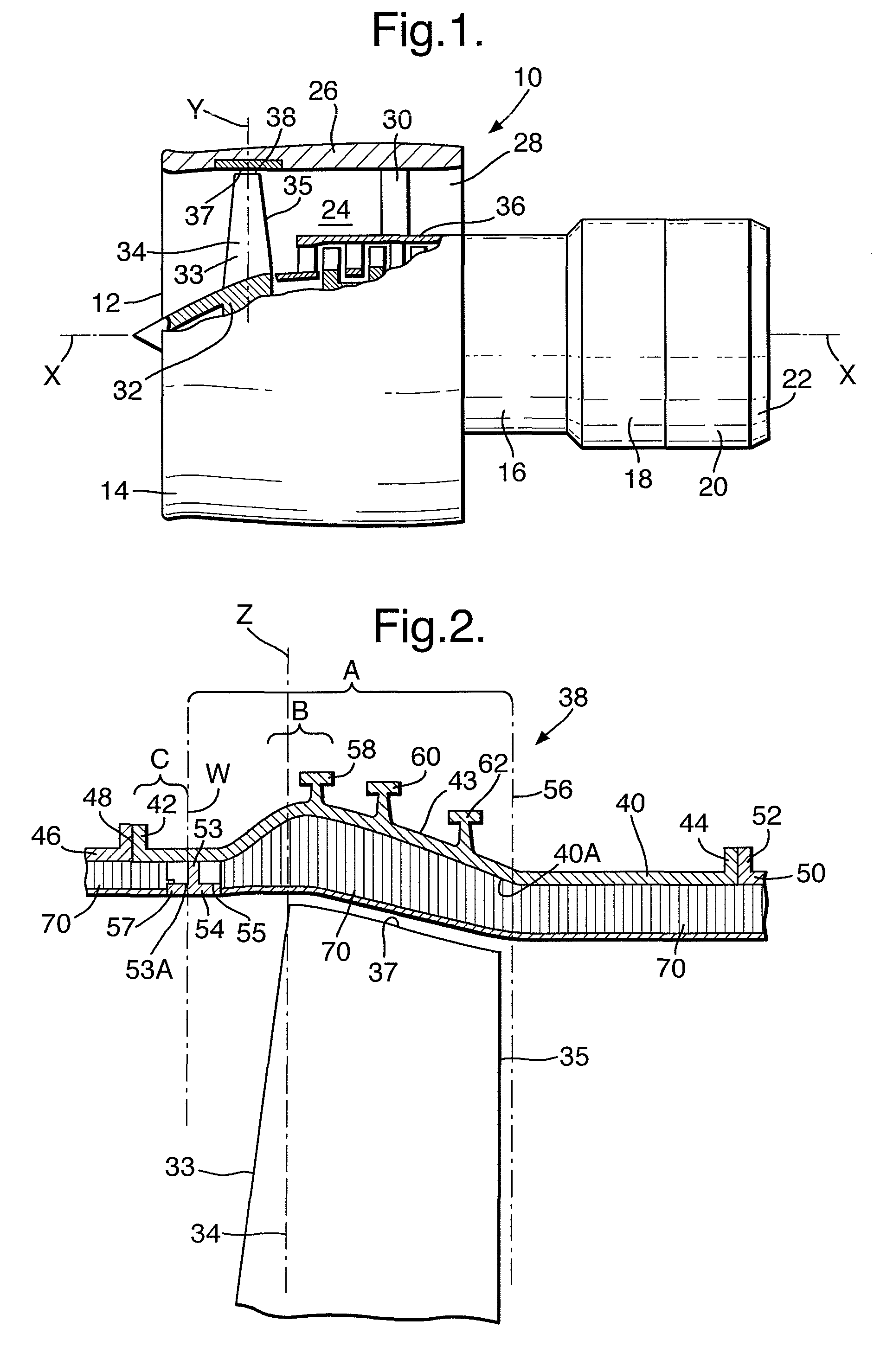
[0043]A turbofan gas turbine engine 10, as shown in FIG. 1, comprises in flow series an intake 12, a fan section 14, a compressor section 16, a combustor section 18, a turbine section 20 and an exhaust 22. The turbine section 20 comprises one or more turbines arranged to drive one or more compressors in the compressor section 16 via shafts. The turbine section 20 also comprises a turbine to drive the fan section 14 via a shaft. The fan section 14 comprises a fan duct 24 defined partially by a fan casing 26. The fan duct 24 has an outlet 28 at its axially downstream end. The fan casing 26 is secured to the core engine casing 36 by a plurality of radially extending fan outlet guide vanes 30. The fan casing 26 surrounds a fan rotor 32, which carries a plurality of circumferentially spaced radially extending fan blades 34. The fan rotor 32 and fan blades 34 rotate about the axis X of the gas turbine engine 10, substantially in a plane Y perpendicular to the axis X. The fan casing 26 als...


PUM


Abstract

A turbofan gas turbine engine (10) comprises a fan rotor (32) carrying a plurality of radially extending fan blades (34). A fan blade containment assembly (38) surrounds the fan blades (34) and the fan blade containment assembly (38) comprises a generally cylindrical, or frustoconical, metal casing (40). The casing (40) comprises an annular member (54) positioned axially upstream of the tip (37) of the fan blade (34). The annular member (54) extends in a radially inwardly and axially downstream direction from the metal casing (40) towards the tip (37) of the fan blade. A set of cassettes (120) carries fan blade track panels (71B, 71C, 71D). The cassettes (120) are secured to the metal casing (40) by axially extending members (124, 128) on the upstream and downstream ends (122, 126) of the cassettes (120) which locate on the annular member (54) and are secured to inserts (136) on the inner face of the casing (40).

Description

CROSS-REFERENCE TO RELATED APPLICATIONS[0001]This application claims priority to GB 0324549.5, filed 22 Oct. 2003.BACKGROUND OF THE INVENTION[0002]The present invention relates to gas turbine engine casings, particularly for gas turbine engine fan casings and turbine casings, more particularly to an improved acoustic liner or an improved rotor blade track liner for use within the gas turbine engine casing.[0003]Turbofan gas turbine engines for powering aircraft conventionally comprise a core engine, which drives a fan. The fan comprises a number of radially extending fan blades mounted on a fan rotor enclosed by a generally cylindrical fan casing. The core engine comprises one or more turbines, each one of which comprises a number of radially extending turbine blades enclosed by a cylindrical, or frustoconical, casing.[0004]The fan casing is provided with a hook axially upstream of the tips of the fan blades to prevent upstream movement of a detached fan blade.[0005]There is a requi...

Claims


Application Information

Patent Timeline
Patent Type & Authority Patents(United States)
IPC IPC(8): F01D25/24F02C7/045F04D29/66
CPCB64D33/02F01D25/246F02C7/045F04D29/664B64D2033/0206B64D2033/0286Y02T50/672Y02T50/60F01D25/24F04D29/403F04D29/526F04D29/541
Inventor HARPER, CEDRIC BCREAGH, MICHAELHUMPHRIES, NEILMARTINDALE, IAN G
Owner ROLLS ROYCE PLC
Why Eureka
Try Eureka